A portable VHP load configuration is defined by far more than how many items sit in the room: vapor distribution depends on item type, quantity range, orientation, spacing, which surfaces stay open or closed, where items touch each other or their supports, and whether items are packaged. Those variables decide where hydrogen peroxide vapor reaches freely and where it is shadowed by a dense stack, a rear face turned toward a wall, or a contact point between two trays. Fix those variables in a written load map before qualification, because the distribution evidence you generate applies to the arrangement actually challenged and not to a rearranged version of it.
Define the Representative Load Beyond Item Count
| Load factor | Definition to freeze | Decision boundary |
|---|---|---|
| Item type | Item types included in the intended load | Evidence applies to the challenged item mix |
| Quantity range | Quantity range intended for use | Qualification should cover the intended process conditions |
| Orientation | Fixed orientation for each item type | A new orientation can change which surfaces are screened |
| Spacing | Defined spacing between items | A denser arrangement can alter vapor paths |
| Surface state | Surfaces that remain open or closed | Open and closed exposure states are not equivalent |
| Contact state | Surfaces touching other items or supports | Contact points are plausible weak-access locations |
| Packaging state | Packaged or unpackaged state for each item type | A packaging change can alter exposure paths |
A representative load is a frozen description of an arrangement, not a quantity. Counting ten carts tells you nothing about whether vapor reaches the underside of the lowest shelf; the same ten carts pushed together against a wall present a different exposure problem than the same ten spaced across the room with their faces open.
The reason each configuration variable matters is physical. Vaporized hydrogen peroxide moves by bulk air motion and diffusion, and it is consumed on the surfaces it contacts. A surface buried inside a nested stack sees vapor only after it has passed over everything upstream, so concentration and contact time at that surface are lower than at an exposed face in the open room. Orientation decides which faces are exposed and which are screened. Spacing decides whether vapor can circulate between items or must diffuse into a dead volume. Packaging decides whether a surface is part of the room at all during the cycle.
Surface state and contact state deserve separate attention because engineers often treat them as the same thing. An open container presents its interior to the room; a closed one presents only its exterior, and the interior is outside the challenge entirely. A contact point, where a tray rests on a rack rail or two bins touch, is a surface that is nominally open but has almost no vapor access. Both conditions have to be written down, item type by item type, because a reviewer reading the qualification record later must be able to tell whether a given surface was challenged, excluded, or simply never considered.
Quantity range matters in the opposite direction from intuition. The heaviest load is not automatically the worst case for every surface: a near-empty room with one item pushed into a corner behind a large skid can be harder to reach than a full room with even spacing. Define the range you intend to run and establish which end of it, or which pattern within it, presents the weakest vapor access.
Map Shadowed Surfaces, Contact Points, and Blocked Vapor Paths
Before placing a single sensor or indicator, walk the loaded room and mark the places where vapor access is plausibly weakest. This map, not a grid of evenly spaced points, is what makes the loaded study meaningful.
The locations worth marking follow from how the load obstructs flow. Nested items, where one container sits inside or directly on another, create interior surfaces with a single narrow path for vapor exchange. Rear faces turned toward a wall, a column, or a large piece of fixed equipment are screened from the generator’s discharge and from the room’s circulation pattern. Contact points, including the footprint where an item rests on a shelf, the line where two bins meet, and the area under a leveling foot, have almost no exposed area at all. Dense corners accumulate items and lose air movement at the same time. Zones behind large equipment, such as a filling line frame, a tank, or a mobile cart loaded to full height, are screened by the equipment itself regardless of how many items sit there.
Blocked vapor paths are a separate category from shadowed surfaces and deserve their own marks. A load that fills the space between the generator discharge and the far wall, or that sits across a return path, changes the room’s circulation rather than just hiding a few square centimeters. When the load itself alters the flow field, the weakest location may be well away from the densest stack, downstream of whatever the load is diverting flow around. Position the generator and any distribution fans in the load map as well, since where the unit stands is part of the configuration.
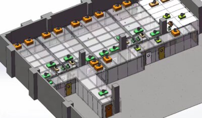
Document the map with enough detail to rebuild it: a plan sketch showing item positions and the generator’s location, plus a short written description of each marked location and why it was judged weak. That reasoning is what a change reviewer will need later, when someone proposes moving a rack.
Arrange Items So the Intended Configuration Can Be Reproduced
Reproducibility is an arrangement problem, and the fix is to make the correct position physically obvious rather than relying on a written instruction. If an operator cannot tell whether a cart is in the qualified spot, the load map is a description of one historical cycle rather than a specification.
Practical measures are mechanical. Mark floor positions for mobile items so a cart returns to the same footprint and the same clearance from the wall. Specify the shelf level and the facing direction for items whose orientation changes which surfaces are screened. State the minimum gap between items, rather than describing the arrangement as “spaced,” because a gap that closes to zero converts an open face into a contact point. Where a lid, door, or drawer must stay open during the cycle, say so explicitly for each item type and specify how it is held open, since a lid that swings shut mid-cycle removes a surface from the challenge without anyone noticing.
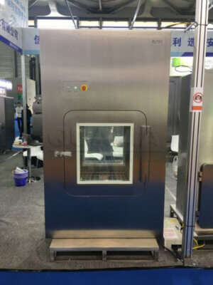
The same discipline applies to what is not in the room. If the qualified configuration assumes certain equipment is removed, covered, or powered down, that belongs in the load map, because a piece of ancillary equipment wheeled in for convenience creates a new shadow that nobody evaluated. Transfer devices feeding the same space, such as a VHP pass box with its own defined load pattern, are qualified separately and do not extend their evidence into the room.
Finally, write the load map so that someone who was not present at qualification can set it up. Item type, quantity range, orientation, spacing, open or closed state, contact points, and packaging state are the seven things a setup sheet has to carry. If any of them is left to judgment at the time of loading, the configuration is not frozen.
Challenge Hard-to-Reach Locations With Measurements and Indicators
| Evidence element | Role at hard-to-reach locations | Interpretation limit |
|---|---|---|
| Physical measurements | Assess distribution at appropriate locations under the representative load | Interpret results against the critical process parameters and equipment-specific limits defined in the qualification protocol |
| Suitable biological indicators | Where appropriate, challenge selected locations with plausibly weak vapor access | Biological-indicator evidence does not replace critical process parameters or process design |
| Frozen load map | Confirm the challenged item type, quantity range, orientation, spacing, surface state, contact state, and packaging state | Evidence remains tied to the configuration that was actually challenged |
The purpose of a loaded-cycle challenge is to see what happens at the locations the load map identified as weakest, which means placing instruments and indicators where access is poor rather than where they are convenient to reach. A sensor in the center of an open aisle confirms that the generator ran; it says little about the underside of the lowest shelf.
Physical measurement and biological challenge do different work. Hydrogen peroxide concentration and the room’s temperature and relative humidity are continuous, quantitative, and tied to the critical process parameters that the cycle is designed to deliver. EU GMP Annex 1 describes sterilization validation for sterile medicinal product manufacture as using physical measurements together with, where appropriate, suitable biological indicators at appropriate locations, and it is explicit that biological-indicator evidence does not substitute for the critical process parameters or for sound process design. In a loaded room that distinction is practical: an indicator placed at a contact point gives a single pass-or-fail outcome for that spot, while the physical record shows whether the cycle delivered the intended conditions in the room at all.
Annex 15 of EudraLex Volume 4 frames the staging. Operational qualification challenge testing can include operating limits or worst-case conditions, and performance qualification runs across the intended process conditions. Applied to a portable generator in a loaded room, that supports challenging the configuration you judged weakest during development work, then demonstrating the cycle across the intended range of loads in performance qualification. The acceptance limits for concentration, exposure time, and indicator outcome are equipment-specific and belong in the project’s approved protocol, not in a general discussion of method.
Record the load map alongside the measurement and indicator results, in the same document set. The evidence is tied to the configuration challenged, and separating the two makes it impossible to tell later which arrangement a passing cycle actually covered. Whether the resulting data supports release of the cycle for routine use is a decision for the project’s approved qualification procedure and its designated approver.
Compare Empty and Loaded Cycle Evidence Without Assuming Equivalence
| Evidence condition | What the evidence represents | Applicability boundary |
|---|---|---|
| Empty-room cycle | The chamber without the intended representative load | A passing result does not establish performance for a loaded configuration |
| Loaded cycle | Distribution evidence for the representative worst-case load actually challenged | The result applies to that load map and does not automatically cover a changed pattern that alters exposure paths |
An empty-room cycle and a loaded cycle answer different questions, and the first does not answer the second. An empty-room run characterizes the generator, the distribution equipment, and the room envelope: injection rate against room volume, how quickly concentration rises, where condensation appears on cold surfaces, and how long aeration takes with nothing absorbing peroxide. That is useful baseline information and it is the right way to establish that the equipment and the room work together.
What the empty run cannot show is the effect of the load. Items introduce surface area that consumes hydrogen peroxide, they obstruct circulation, and they create the shadows, contact points, and dead volumes that the load map identified. A room that reaches its target concentration quickly when empty can behave differently once racks, carts, and packaging are in place, because the same injected mass is now distributed over more surface and through a more restricted flow field. Extending a passing empty-room result to a loaded configuration skips exactly the mechanism that makes load configuration a design question.
The practical consequence is that the empty-room record belongs in the file as equipment characterization, and the loaded record is what supports routine operation with that load. When both exist, compare them deliberately: a large gap in time to concentration, in distribution uniformity, or in aeration duration between empty and loaded runs tells you how much of the cycle’s margin the load is consuming, and whether the configuration is close to the limit of what the portable unit can deliver in that volume.
Trigger Change Review When the Load Pattern Alters Exposure
Treat any proposed change to the load pattern that could alter vapor exposure paths as a change-control question, and answer it before the next cycle runs. The test is not whether the change looks significant but whether it moves, adds, or removes a surface that vapor has to reach.
Several ordinary operational changes meet that test. Adding an item type that was not in the qualified mix introduces new surfaces and new shadows. Increasing quantity beyond the qualified range tightens spacing. Reorienting an item turns an exposed face into a screened one. Changing packaging, including a switch to a different film, bag, or tray, can close a path that was previously open, or open one that was closed. Moving a large piece of equipment, or relocating the generator itself, redraws the flow field for everything downstream. Substituting a material with different peroxide absorption changes how much vapor the load consumes even if the geometry is unchanged.
The review decides one thing: whether the existing distribution evidence still covers the new arrangement, or whether additional study is needed, and if so, what kind. A change that only reduces load density within the qualified pattern may be covered by existing evidence; a change that creates a shadowed location not represented in the original challenge generally is not. That determination, and any decision to run the changed configuration before new evidence exists, sits with the project’s approved change-control procedure and its designated approver.
To make that review quick rather than a research exercise, keep the frozen load map, the sketch of challenge locations with the reasoning behind each, the physical and indicator results tied to that configuration, and the empty-room baseline together in one place. When a change is proposed, bring those records plus a description of the new arrangement, the room volume and air change pattern, the generator model and its position, and the materials involved, so the reviewer can judge the exposure question on the configuration itself rather than on recollection.
Frequently Asked Questions
Q: Is the highest item count always the worst-case portable VHP load?
A: No. The more challenging load may be the configuration that creates the weakest vapor access, such as dense spacing, nested items, contact points, rear faces, or surfaces screened by large equipment. Define the proposed worst case by its item mix and arrangement, then freeze that exact load map for qualification.
Q: Can one qualified load cover different orientations or packaging states?
A: Only when the qualification evidence supports the intended conditions. A different orientation or a change between packaged and unpackaged items can alter exposure paths, so compare the new configuration with the challenged load map and use change review to decide whether additional study is needed.
Q: What should be checked before recreating a qualified load for routine use?
A: Confirm the item types, quantity range, orientation, spacing, open or closed surfaces, contact states, and packaging states against the frozen load map. Record any deviation and review it before relying on existing evidence if it changes which surfaces are screened or how vapor can reach them.
Q: How should challenge locations be selected for a loaded cycle?
A: Select locations where vapor access is plausibly weakest, including nested areas, rear faces, contact points, dense corners, and zones screened by large equipment. Use physical measurements and, where appropriate, suitable biological indicators, then interpret both against the critical process parameters and equipment-specific limits defined in the qualification protocol.