
In-situ filtration belongs on the exhaust branch that carries contaminated or hazardous air away from a containment device or room, placed where the filter can be tested while installed and where the housing can be opened without exposing the surrounding space. In practice, the location is fixed by three properties you can look up or define: which stream the filter actually serves, how much unfiltered duct remains upstream of the housing, and whether the work done at the housing is limited to installed testing or also includes removing a loaded filter. “In situ” describes work performed on the filter while it sits in its housing in the duct — most often integrity testing with an upstream aerosol challenge and a downstream scan or probe — and it says nothing on its own about how the filter is handled when it comes out.
Trace the exhaust stream before choosing the filter location
Start by drawing the exhaust from its source to its discharge point, because the filter duty follows the stream, not the room. In a biosafety laboratory project it is common to find two separate streams on the ventilation drawings: the general room exhaust, and the exhaust from a primary containment device such as a cabinet or isolator that is hard-ducted out. These are different design questions with different evidence attached, and treating them as one is how a project ends up with a filter in the wrong branch.
Trace both to their discharge and mark, for each, whether a filter is required and where an installed test would physically be performed. The BMBL’s BSL-3 guidance addresses HEPA or equivalent filtration and periodic filter testing for certain primary-barrier exhaust applications, and that guidance applies to that exhaust context. The laboratory’s inward-airflow requirement is a separate facility check on the room, verified by airflow direction evidence rather than by a filter certificate.
The second part of the tracing exercise is the duct itself. If the design team proposes putting the housing at the containment boundary, sketch the duct run; then sketch it again with the housing moved downstream into a plant room or on the roof, and mark every space the unfiltered duct now passes through. Moving the housing downstream often improves physical access for testing and changeout and can simplify structural support, at the cost of a longer run of duct carrying untreated air through spaces that may be occupied. Consider a two-story facility where the containment room sits on the first floor and the fan is on the roof: a boundary-mounted housing keeps the untreated section to a short stub, while a roof-mounted housing puts a full vertical riser and a horizontal run under negative pressure between the room and the filter. Both arrangements exist; the decision is where you want the untreated length, how that duct is sealed and tested, and where isolation dampers sit relative to the housing so the filter can be isolated for service.
Distinguish biosafety laboratory and hazardous pharma duties
| Exhaust stream | Start with | Verify for the selected housing |
|---|---|---|
| BSL-3 room exhaust | Required inward airflow and the facility exhaust design basis | Confirm which branch calls for filtration and what room-airflow evidence is separate from installed filter evidence |
| Certain BSL-3 primary-barrier exhaust | Applicable BMBL guidance on HEPA or equivalent filtration and filter testing | Identify the device exhaust path and the installed filter covered by the test |
| Hazardous pharmaceutical dust exhaust | Discharge hazard and worker exposure during filter removal | Identify the final HEPA duty and safe-change provision under the applicable project basis |
Biosafety exhaust and hazardous pharmaceutical exhaust ask the filter to answer different questions, and the housing has to satisfy whichever applies to your project. Biosafety work is organized around preventing release of an infectious agent and around maintaining the facility’s airflow direction; hazardous pharmaceutical work is organized around an occupational exposure target for a potent compound and around the discharge of hazardous dust. The filter element may look similar in both cases. The arrangement around it usually does not.
For pharmaceutical exhaust carrying hazardous dust, begin with the release hazard at discharge and with the exposure risk to the person who eventually removes the loaded filter, then compare a safe-change housing against whatever in-situ service arrangement the site has proposed. The WHO GMP guidance for pharmaceutical products containing hazardous substances describes final HEPA filtration and safe-change provisions for such exhaust, including access for installed leakage testing and monitoring of the filter bank. Those are two provisions, not one, and a housing that offers a test port but no contained removal method answers only half of the guidance for that application. A bag-in/bag-out housing exists precisely because the loaded filter medium, not the airstream, becomes the exposure source at changeout.
On the biosafety side, read the same housing against a different set of records. The filter branch carries the filtration and installed-test duty; the room carries the inward-airflow duty. When a project team collapses these, it typically shows up at handover as a single commissioning report that is asked to prove both things at once and proves neither cleanly. Keep the question “which branch calls for filtration” separate from “how is directional airflow demonstrated for this room,” and the housing specification stays tractable.
Check which work can be done in place
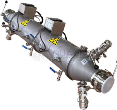
The phrase “in situ” covers a range of capabilities, so the useful question is which specific operations can be performed on the installed unit without taking it out of the duct. Integrity testing is one: an upstream injection point, adequate mixing length and a downstream scan or sample point let the installed filter and its seal be challenged where it sits. Decontamination before service may be another, depending on whether the housing has gas-tight isolation and ports for a decontaminating agent. Filter removal is a third, and it is governed by different hardware entirely.
Ask the vendor to say, item by item, what can be done on the installed unit, and ask for a service drawing that shows how the filter is handled at the moment the housing is opened. A housing with a test section demonstrates that the installed filter and its gasket seal can be challenged; it does not by itself describe what protects the technician from the loaded medium during removal. That is determined by the access method — a bagging ring and continuous-liner arrangement, a gasketed door opening into a controlled space, or something else — and by whether the branch can be isolated and, where the hazard calls for it, decontaminated beforehand.
Two further details belong on the same drawing. First, the clearance envelope: a bag-out procedure needs working room in front of the access door that a tight plant room or a roof curb may not provide, and this is easier to fix on paper than after installation. Second, the sequence of isolation. If the housing sits on a branch that must stay under negative pressure while adjacent spaces remain occupied, the drawing should show which dampers close, which fan continues to run, and what the branch pressure is during the opening. Whether a decontaminated housing may be opened, and whether a replaced filter may be returned to service, are decisions that belong to the project’s approved procedure and its designated approver, not to the housing specification.
Keep the fan duty and the installed test in view
A filter housing on an exhaust branch is both a resistance in the system and a piece of equipment that needs physical access, and both constraints have to reach the fan designer before the duct layout is frozen. HEPA media resistance rises as the filter loads, so the fan has to deliver the required airflow at the clean condition and still deliver it at the design end-of-life condition. If the branch helps maintain a pressure cascade between the containment space and its surroundings, that cascade depends on the exhaust volume holding steady across that resistance range, which in turn depends on the fan curve, the control method and the available static pressure margin.
Review both conditions explicitly with the fan designer: the airflow required at clean filter resistance and the airflow required at the loaded filter resistance that triggers changeout. The gap between them is what the fan or its speed control has to absorb. A branch sized only for the clean condition will drift as the filter loads, and the first observable symptom is usually a weakening differential pressure between the containment space and the adjacent corridor rather than anything visible at the filter itself. Differential pressure monitoring across the filter bank is what makes the loading state visible, and it is worth specifying alongside the test section rather than after it.
Access deserves the same reservation of space. The test connections — upstream injection and downstream sampling — need defined positions with enough straight duct for the challenge aerosol to mix, and the downstream side needs room for a person and an instrument. Reserve that space in the layout at the same time you reserve the service clearance for the access door; both tend to be the first dimensions sacrificed when a plant room gets tight, and both are expensive to recover later. By the time you hold a design review on this, it helps to arrive with the exhaust single-line drawing, the required airflow for each branch, the pressure relationships the branch supports, the available static pressure, and the hazard or exposure basis for the stream, because the housing family and the service arrangement follow from those five facts.
Separate filter, housing and airflow evidence at handover
At handover, keep three records separately identifiable: the filter element’s classification, the installed filter leakage result, and the evidence of required airflow direction. Each describes a different boundary. Bundling them into one commissioning report makes it impossible for the buyer to see which of the installed exhaust duties has actually been verified and which still needs work.
The filter element classification is a property of the filter as manufactured. ISO 29463-1:2024 covers performance-based classification of high-efficiency filters along with marking and documentation of test results, so the element certificate tells you what grade of medium was supplied and how it was classified. It describes the filter that arrived on site. It does not describe the seal between that filter and the housing, or the condition of the duct around it.
The installed filter leakage result describes that second boundary — filter, gasket, frame and housing together, as installed in the duct and challenged in place. This is the record that corresponds to the in-situ test section, and it is specific to one filter in one housing at one date. If a filter is replaced, the previous result no longer describes the installed condition.
Airflow direction evidence describes the third boundary: the room or the containment space and its relationship to adjacent areas. This is the facility check that the BMBL treats separately from primary-barrier exhaust filtration, and it is demonstrated by airflow measurement or visualization rather than by anything the filter certificate contains. Ask for these three as three documents, each naming the specific filter, housing tag or room it refers to, and the gaps in the installed exhaust duties become visible on the day you receive them rather than during the first periodic retest.
Frequently Asked Questions
Q: What should I bring to the first coordination meeting if the housing has not been selected?
A: Bring a marked-up exhaust schematic with separate tags for room and equipment streams, plus a floor plan showing candidate service access. Those two drawings let facilities and biosafety staff discuss location and exposure before a vendor model constrains the layout.
Q: Can one proposed location serve exhaust streams with different duties?
A: Keep it as an option only while the drawings and design basis clearly identify each connected stream and the duties the shared location must meet. If one branch changes the release or maintenance boundary, take that difference back into the layout review.
Q: Who should resolve a conflict between the best duct route and the best filter-removal route?
A: Have the ventilation and service teams review both routes on the same drawing with the responsible safety team. Mark which move changes the untreated duct path and which changes the handling area so the design decision addresses both consequences.