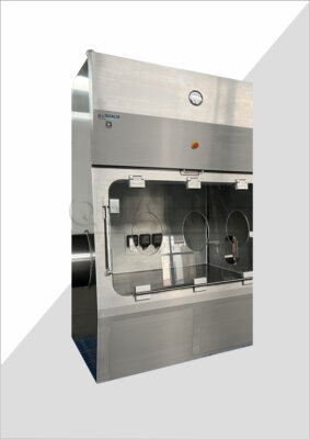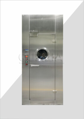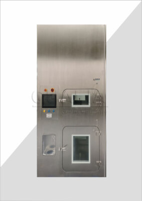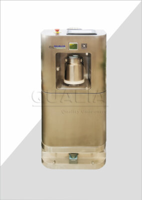


A Vacu-Pass wall opening and sleeve design starts from the cable schedule, not from a convenient hole size: the number of cables, their measured outside diameters, connector dimensions, routing direction and any reserve capacity determine the penetration arrangement, and the arrangement then determines the sleeve envelope. Two site conditions change the answer materially: the actual wall construction and thickness, which set what the sleeve can be anchored to and how deep it must run, and whether cables alone or mixed services cross the same boundary, since a cable-only port and a mixed-service transit are different sealing products with different documented scopes. A sleeve here means the fixed element built into or through the wall that receives the sealing assembly and presents a defined interface to the building fabric.
Translate the cable schedule into the opening requirement
The opening requirement is an output of the cable schedule, so write the schedule first and size the penetration from it. The schedule should name each cable or cord, its actual outside diameter rather than a nominal catalogue figure, the connector or plug that has to pass through or be terminated on one side, the direction and route the cable takes on each face of the wall, and the spare capacity the project wants to hold. Only when those entries exist can the required penetration arrangement — one port, several ports, or a port plus reserve positions — be defined and dimensioned.
The order matters because the building detail is poured, blocked out or framed long before cabling is finalized. An opening fixed ahead of the service schedule tends to lock in the sealing system that fits that hole, and any later change in cable count or diameter then has to be absorbed by whatever assembly was already installed. Working the other way round keeps the choice of sealing arrangement open while it still costs nothing to change.
Reserve capacity deserves a precise description in the schedule rather than a general allowance. Reserving space is a design decision about how much unused sealing volume or how many blanked positions the arrangement carries; it is not evidence that an unspecified future cable, with an unknown diameter and an unknown connector, will fit that space or be usable with the installed assembly. State the reserved quantity and the diameter range it is intended to accept, and treat anything outside that range as a new design case.
Connector geometry is where cable schedules most often fall short. A cable that passes a diameter check may still be impossible to install if its moulded connector cannot pass the sleeve bore and the sealing element has to be fitted over a continuous cable length. Record for each cable whether the connector passes through the opening, whether it is terminated after installation, or whether a split sealing arrangement is required, because that single fact can change the product family selected.
Coordinate the sleeve with the actual wall construction
Before the sleeve envelope is fixed, produce a dimensioned interface drawing that records the wall construction, its total thickness, the opening position in three dimensions, the structural support available around the opening, and the access available on each face. The sleeve has to meet a real construction interface — a cast-in-place concrete wall, a sandwich panel partition, a modular laboratory wall panel, a blockwork wall with a finish applied — and each of these presents a different fixing method, a different edge condition and a different way of making good around the penetration.
Thickness drives more than sleeve length. It sets whether the sealing assembly sits fully within the wall zone or projects on one or both faces, whether the cable has a straight pull through the penetration or has to bend immediately behind the wall face, and how much working room an installer has to compress or close the sealing elements. Position matters for the same practical reason: an opening set close to a corner, a floor, a service riser or a door frame can be dimensionally correct and still leave no room for a tool or a hand on the containment side.
Mark the drawing with revision identification and show the interface between the equipment and the building construction explicitly — the convention described in the US guide specification UFGS 01 33 00 for shop-drawing submittals, where dimensioned and revision-identified interfaces connect equipment to building construction. That document is an editable US guide specification rather than a universal requirement, but the practice it describes gives both the sleeve supplier and the building contractor a single controlled drawing to work from.
In a retrofit, concealed conditions are the recurring risk: reinforcement, embedded conduit, cavity construction, or a finish that hides the real substrate. Keep those conditions on the drawing as explicit survey actions with a named party and a date, not as assumptions carried into the design. An assumed generic wall is the fastest way to arrive on site with a sleeve that cannot be anchored where the drawing shows it.
Compare combined and separate service crossings
Where several services could cross the same boundary, compare a defined combined transit against separately routed penetrations using the actual service schedule and the documented scope of each candidate sealing system. The Swiss Expert Committee for Biosafety recommendation on structural and technical safety measures in BSL-3 laboratories favors minimizing the number of penetrations through the laboratory envelope and considering spare openings at the design stage, which argues in principle for grouping services. That guidance is a nonbinding Swiss recommendation for BSL-3 laboratories and does not establish that any particular combined opening is suitable.
The functional difference is straightforward. A combined transit asks one sealing assembly to accommodate several items of different diameter, stiffness, surface finish and thermal behavior within a shared frame, and its documented scope has to state which of those items it accepts. Separate penetrations give each service its own sealing arrangement matched to that service, at the cost of more openings in the wall and more individual interfaces to detail, seal and verify. Grouping reduces the count of building penetrations; separating keeps each sealing arrangement within a narrower, better-defined duty.
The decision rule follows from documentation rather than from preference. If a combined arrangement is proposed, the sealing system’s own documentation must cover the full mix of items in the service schedule. A cord and cable port is specified for cables and cords; do not assume it accepts pipes, tubing, ducted services or a mixed population without documentation from the proposed system that states so. Where that documentation does not exist for the actual mix, separate penetrations matched to each service type are the defensible starting arrangement.
Reserve openings follow the same logic. A spare opening is useful when its intended service type and size range are declared, and the blanking arrangement for the unused state is part of the specified system. An undeclared hole kept “for later” is an unsupported sealing arrangement waiting to be discovered during commissioning.
Assign sleeve and wall-seal responsibilities
Name an owner for every element of the penetration before the order is placed, because a purchased port can leave a separate leakage path at the building interface if the supplier’s scope stops at the supplied component. The elements to allocate are the sleeve itself, its anchorage into the structure, the seal between the wall and the sleeve, the seal between the cables and the sealing assembly, the final making-good and finishing of the wall around the penetration, and the testing responsibility for each of those interfaces. Each needs a named party and an agreed connection detail showing how one party’s work terminates and the next begins.
The cable seal and the wall-to-sleeve seal are distinct physical barriers, and they are often supplied and installed by different trades. A cable port can be correctly installed and its cable seals correctly closed while the annulus between the sleeve and the wall construction remains unsealed, or sealed with a material that no one specified. Writing both seals into the responsibility matrix, each with its connection detail, is what prevents that gap.
This is the same allocation discipline that the Asian Development Bank’s user’s guide to procurement of plant for design, supply and installation describes for plant contracts: setting out the interfaces between the employer, the supplier and other contractors explicitly before bidding. That 2016 procurement template does not determine how any particular project allocates work — the actual contract does — but it makes the point that unallocated interfaces are a procurement problem, not a site problem.
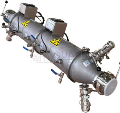
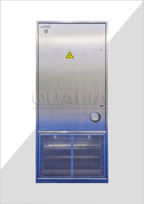
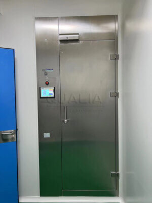
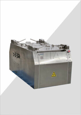
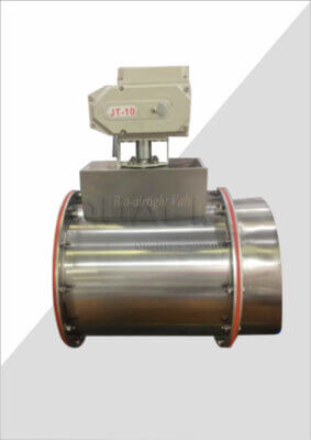
A single contracted package can legitimately combine several of these responsibilities under one supplier, and that is often the simplest arrangement where the wall and the penetration are built together. Even then, the package scope has to identify each element individually rather than describing the work as supply and installation of a port, so that the testing responsibility and the making-good are traceable to a named obligation. A QUALIA Vacu-Pass cord and cable port is identified as the product in that schedule; the project-specific wall and sleeve interface detail is then requested against the recorded wall construction and cable schedule.
Plan documented access for future cable changes
Show on the design how a cable will be added, removed or replaced later: the service access available on each face, the intended spare arrangement, and the boundary of the procedure that a future change has to follow. Physical space alone does not make a change possible. A spare position is usable only when the chosen sealing assembly has a documented method for opening it, inserting the cable, and restoring the seal, and that method differs between sealing systems.
Different assemblies behave differently here, and the difference is functional rather than cosmetic. Some sealing arrangements are designed to be opened, reconfigured around a new cable population and reclosed; others are fixed once made and are not intended for reconfiguration. Ask the supplier which of these the proposed assembly is, and obtain the documented re-entry method if it is reconfigurable, because that answer determines whether “spare capacity” means a usable future route or simply unoccupied volume.
Where the arrangement is fixed and non-reconfigurable, plan a different change strategy from the outset rather than discovering the constraint during a later installation. That might mean installing the full anticipated cable population at first fit, or providing a separate, independently sealed penetration dedicated to future work. Either way the choice is made at design stage, when it is a drawing change rather than a wall opening.
Any work that breaks and remakes a containment penetration also crosses an approval boundary. Record on the design which procedure governs re-entry and who approves the return of that boundary to service, and leave the method and acceptance of that re-approval to the project’s approved procedure and its designated approver.
Separate local leak checks from room-boundary verification
| Check | Verification boundary | Project scope to confirm |
|---|---|---|
| Local leakage check | Local leak location at the penetration | Define the local check under the applicable jurisdiction, project risk assessment and approved protocol. |
| Assembled-room tightness verification | The completed room boundary | Establish whether room-level verification is required and define its method and acceptance values under the applicable project protocol. |
Treat inspection of the installed components, local leakage checking at the penetration, and verification of the completed room boundary as three separate tasks with three separate records. The Swiss Expert Committee for Biosafety recommendation for BSL-3 laboratories distinguishes local leak location from final tightness testing of the assembled room, and it also calls for retesting after repair. Conflating them is what allows a penetration that passed a local check to be treated as evidence about a room that has not been tested.
Component inspection comes first and is largely visual and dimensional: the sleeve is installed in the recorded position and orientation, the anchorage is as detailed, the sealing elements match the cables actually installed, and the materials used at the wall-to-sleeve interface are those specified. Material resistance belongs in this check too, since the Swiss recommendation addresses the resistance of materials used in the laboratory envelope to the decontamination and cleaning agents the room will see. Record the materials actually installed, not the ones originally specified, because substitutions made on site change what the boundary has to withstand.
The two leakage-related checks answer different questions over different boundaries, and the project information needed to define each is different as well. Neither the method nor the acceptance values are transferable from one project to another: the applicable jurisdiction, the project risk assessment and the approved test protocol determine both, and the Swiss recommendation is a nonbinding engineering recommendation rather than a source of acceptance thresholds.
Build the reassessment trigger into the acceptance plan. If the penetration is repaired, if a sealing element is replaced, or if a material at the interface is changed after the first check, the affected verification is repeated before the boundary is treated as complete; whether that means repeating the local check alone or also the assembled-room test is a decision for the approved protocol and its designated approver. For the supplier discussion that fixes all of this, have ready the cable schedule with measured diameters and connector details, the dimensioned wall interface drawing with construction and thickness, the service mix crossing the boundary, the responsibility allocation for sleeve and wall seal, and the test scope the project intends to apply at the penetration and at the room.
Frequently Asked Questions
Q: Can the wall opening be finalized while the cable selection is still changing?
A: Keep it provisional until the cable quantities, actual sizes, connector constraints, routes and intended spare capacity are defined. Record unresolved cable choices on the dimensioned wall detail so an assumed opening does not become a construction commitment before the penetration arrangement is confirmed.
Q: Can an existing sleeve be retained for a Vacu-Pass retrofit?
A: Treat it as an interface to verify, rather than assuming it is suitable. Check its actual dimensions, the surrounding wall construction and thickness, available support and service access against the proposed assembly detail. Keep concealed conditions as explicit survey actions until they are verified.
Q: Does leaving spare space mean any future cable can be added?
A: No. A later cable must fit the intended arrangement, including its connector constraints, and the selected assembly must have a documented way to accommodate the change. Define the intended spare use and required access; do not treat unspecified future cables as covered by the initial design.
Q: Can pipes share an opening planned for cables?
A: Only consider that arrangement when the proposed system documentation supports the actual combination of services. A cable-only port does not establish suitability for pipes or mixed services. Compare a documented combined arrangement with separate crossings before fixing the opening.
Q: Does purchasing the cable port also settle responsibility for sealing it into the wall?
A: The purchase alone does not establish that scope. Confirm who supplies and installs the sleeve, anchorage, wall-to-sleeve seal and cable seal, and who completes making-good and testing. If one package covers several responsibilities, identify them explicitly so the building interface is not left unassigned.