A cRABS retrofit review is only as useful as the site information it is given. An enclosure concept drawn against an outdated plan, or against an assumed operator position, can look coherent while hiding clashes, unreachable tasks, or transfer routes that cut across the intended barrier boundary. GMP UE Allegato 1 supports considering equipment and material transfer, operator interventions, airflow impact, observation from outside critical areas, cleanable surfaces, and access for operations, maintenance, and repairs when sterile-manufacturing layouts are developed — but it does not define retrofit dimensions, ergonomic reach, installation routes, structural capacity, or project acceptance. The work before a design review is therefore to make confirmed facts, open measurements, and joint decisions distinguishable from assumptions.
Capture the Existing Line and Room Geometry
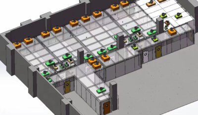
An enclosure boundary can only be evaluated against the room as it actually exists, not as it was originally designed. Current plans, elevations, and sections — where they are available — should show the filling-line envelope, the critical process points, floor and ceiling interfaces, walls, doors, columns, utilities, and any other fixed obstruction that would constrain where panels, doors, or transfer interfaces could sit. Document status matters as much as content: a revision number establishes what was drawn, not what is installed.
Dimensions carried over from a catalogue, a reference project, or a previous line are not a substitute for site data. Where a measurement is missing, the review package is better served by recording it as an open item than by filling it with an assumed value. The register below ties each drawing or field fact to the decision it is expected to inform.
| Input area | Details to show | Design-review use |
|---|---|---|
| Line and room geometry | Current plans, elevations, sections, machine envelope, walls, doors, columns, floor, and ceiling interfaces | Establish the physical baseline and locate conflicts |
| Process and transfer points | Exposed-product locations, feeds, discharge, components, materials, and waste routes | Relate enclosure boundaries to actual operations |
| Operator work | Positions, interventions, tool or part handling, and viewing needs | Review access without assuming a standard operator arrangement |
| Openings and service zones | Doors, panels, glove locations under study, removable items, and component access | Check whether required tasks can be reached |
| Installation path | Delivery, staging, assembly, connection, and removal routes known to the site | Identify access constraints requiring further planning |
| Evidence status | Drawing revision, field confirmation, conflict, and owner | Separate reliable site facts from open measurements |
How the enclosure features themselves relate to that geometry is a separate design question; the essential design features of cRABS for aseptic processing is a useful companion when translating room and line facts into enclosure decisions.
Map Material, Component, and Operator Movements
Geometry alone does not show whether the proposed barrier boundary sits in the right place. The movement picture — normal transfers in and out, component and material replenishment, waste removal, operator positions, interventions, and change-part handling — determines where openings, transfer interfaces, and glove locations may be needed, and which routes cross the proposed enclosure or the background boundary. Annex 1 supports considering equipment and material transfer, operator interventions, and airflow impact in sterile-manufacturing layouts, and it emphasizes controlled movement, transfer risk, and minimized direct intervention. It does not supply the movement map for a specific line; that has to come from the process owner and be reconciled with the current drawing set.
Movements are also time-dependent. A route that is workable during a shutdown may not be workable during filling, and an intervention that occurs only at batch change still shapes access requirements. Recording when each movement occurs, and whether it crosses into the critical zone, keeps the review from treating all access as functionally equivalent.
Retrofits sometimes sit inside a project that also carries a containment objective — an OEB4/OEB5 exposure-control requirement, for example, or a BSL-3/4 laboratory scope. That objective is distinct from aseptic product protection and needs its own containment basis and evidence. A closed RABS configured for aseptic processing does not by itself establish hazardous-material containment performance, and containment scope does not establish aseptic applicability.
Check Installation, Observation, and Service Access
The retrofit has to arrive, be assembled, and then be lived with. Delivery, staging, assembly, connection, and removal routes known to the site should be visible in the information package, because they can constrain panel design or the sequence of installation work. Task-based access then determines whether the enclosure can actually be operated: viewing requirements, door or panel opening zones, glove locations under study, removable items, and the access needed to reach components for cleaning, inspection, maintenance, repair, and reassembly. Annex 1 supports observation from outside critical areas without entry where relevant, and it supports considering maintenance and repair access in the design. It does not set clearance values or ergonomic reach; those remain project-specific.
It helps to organize this section by task rather than by component. For each task, the relevant questions are where the operator or technician stands, what they need to see, what they need to open or remove, and what they need to carry through the opening. Reach, observation, and movement considerations that affect operator position are examined further in the discussion of ergonomics in cRABS.
A task that has no defined standing position, sight line, or access route is an unresolved interface, not a detail that will settle itself at installation.
Resolve Physical Interfaces Before Design Review
The output of this preparation is a marked-up drawing set and a decision log, not a design. Clashes, tasks that cannot be reached, uncertain field conditions, and ownership questions between the site, the process equipment vendor, and the containment supplier should be recorded with the same discipline applied to the geometry itself: what is confirmed, what still needs measurement, who owns the answer, and which decision the answer will feed. That separation keeps assumed conditions from entering the concept disguised as facts, and it makes the remaining disagreements visible while they are still cheap to resolve.
Not every question belongs in the layout package. Acceptance criteria, verification scope, and the evidence expected to demonstrate that the configured enclosure meets the stated protection objective are project confirmation items that run alongside the layout work rather than being settled by a drawing. Once the physical inputs are defined, the Sistema di barriere chiuse ad accesso limitato - cRABS product page is a reasonable next navigation point; envelope, access, and interface details for any specific retrofit remain subject to project design and confirmation.
Domande frequenti
Q: What must a drawing show to make an existing-line layout review useful?
A: Show the machine and room geometry together with critical process points, fixed obstructions, and actual work routes. Plans, elevations, and sections should make the proposed enclosure’s relationship to doors, utilities, floors, ceilings, transfers, and operator positions visible.
Q: Why should we show waste removal and change-part movements as well as product flow?
A: They are part of the work the barrier layout must accommodate. Map replenishment, waste, tools, parts, and interventions where they cross the proposed boundary so the review can consider access and airflow impacts across the full operating sequence.
Q: How do we assess access without assuming a standard clearance or glove arrangement?
A: Describe the actual tasks and mark the locations they need to reach. Include viewing, door and panel openings, cleaning, inspection, repair, and reassembly, then identify uncertain measurements or access conflicts for joint layout review.
Q: What should we do when the drawings do not match the site?
A: Mark the conflict and identify which field condition needs confirmation. Keep drawing revisions, measurement needs, and ownership visible in the review package so a concept is based on confirmed geometry rather than an unresolved drawing assumption.