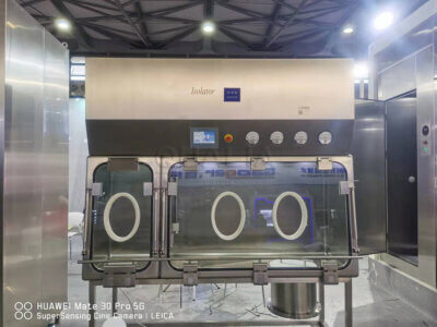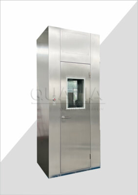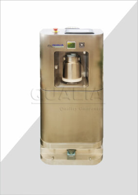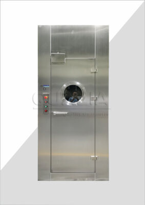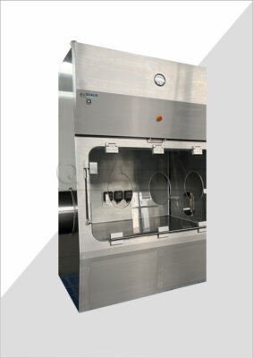

A sterility test isolator that will share a QC lab with existing operations raises a different feasibility question than a new installation in a purpose-built room. The equipment itself may be well understood, but the room, its services, and its current workflows were not designed around it. Before any concept layout can be treated as workable, the project needs to know whether the existing lab can actually receive it without compromising the QC work already running there.
Existing-Lab Survey Data Needed Before Feasibility Review
| Survey area | Evidence to capture | Feasibility question |
|---|---|---|
| Actual room | Room layout and floor and ceiling constraints | Can the proposed isolator concept fit within the actual room constraints? |
| Installation access route | Constraints along the delivery and installation route | Can the isolator reach the proposed location through the available route? |
| Existing services | Utility capacity, HVAC behavior, controls, and heat-rejection conditions | Can the existing services support the proposed retrofit concept? |
| Current QC operations | Current QC flows affected by the retrofit | Can the concept account for the way QC work currently moves through the lab? |
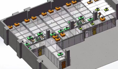
A concept layout drawn from a datasheet and a floor plan tells the project very little about whether an isolator will actually fit and function in a given room. The room as built, with its real dimensions, column positions, floor loading, and ceiling height, often differs from what a general arrangement drawing assumes. Where the proposed isolator has a fixed footprint and a minimum service clearance, even small discrepancies between the drawing and the room change whether the concept is installable at all, or whether it needs to be reoriented, resized, or relocated within the lab.
The same logic applies to how the unit gets into the room. A design that fits the final location is not feasible if it cannot travel through doorways, corridors, lifts, or stairwells to reach that location. Access route constraints are independent of the room’s internal dimensions and have to be surveyed separately, because a route that works for a smaller piece of equipment will not necessarily accommodate an isolator chassis or its packaging.
Utility capacity and HVAC behavior introduce a third kind of constraint, one that is less visible than physical dimensions but equally limiting. An existing QC lab was commissioned to support the loads and air-handling behavior of its original equipment set. Introducing an isolator changes that load profile, and whether the existing supply, exhaust, controls, and heat-rejection capacity can absorb that change is a question the survey has to answer before any interface can be designed with confidence.
Finally, the retrofit does not happen in an empty room. Current QC flows, sample movement, operator paths, and adjacent testing activity all continue around the installation unless the project accounts for them. Capturing how QC work actually moves through the lab today, rather than how it is documented to move, is what lets the project judge whether the proposed isolator concept can coexist with that activity or whether it forces a change to operational sequencing.
Layout, Access, and Workflow Constraints Around the Proposed Isolator
Once survey data exists, the next judgment is whether the proposed layout actually respects the constraints that data revealed, not just whether the isolator fits in isolation. A layout that satisfies floor space on paper can still fail if it blocks an existing access path, conflicts with another piece of equipment’s service clearance, or places the isolator where operator movement for unrelated QC tasks has to route around it continuously.
Workflow constraints are not static once equipment is added. Where the isolator’s location changes how operators move between sample receipt, preparation, testing, and documentation areas, the retrofit effectively redesigns part of the lab’s internal logic, even if no other equipment moves. This matters because QC labs are frequently organized around a sequence of handling steps, and inserting new equipment into that sequence can either preserve the existing flow or disrupt it, depending on where the unit sits relative to the steps on either side.
Access constraints identified during the survey also shape what configuration is realistic. If the access route limits the size or orientation in which the isolator can arrive, the layout has to be designed around that limit rather than around an idealized position. Where the route supports only a particular approach path into the final location, the final position and orientation of the unit may be dictated more by that path than by workflow preference, and the project has to decide which constraint takes priority when they conflict.
The practical judgment at this stage is whether the layout, access route, and current workflow can be reconciled without compromising one of them. Where they cannot be fully reconciled, the project needs to identify which element, the layout position, the access approach, or the workflow sequence, will be adjusted, and confirm that the adjustment is acceptable to the lab’s ongoing operation before the concept is carried into detailed design.
HVAC, Utilities, Controls, and Heat-Load Interfaces
| Interface | Boundary to establish | Condition to assess |
|---|---|---|
| HVAC and exhaust | Existing-system scope and new-system scope | Actual HVAC behavior and the proposed isolator interface |
| Utilities | Existing-system scope and new-system scope | Available utility capacity for the retrofit concept |
| Controls | Existing-system scope and new-system scope | The connection between existing controls and the proposed isolator |
| Alarms and data | Existing-system scope and new-system scope | The connection between existing alarms and data systems and the proposed isolator |
| VHP and room systems | Existing-system scope and new-system scope | How the proposed isolator interfaces with VHP and room systems |
| Heat rejection | Existing-system scope and new-system scope | Actual heat-rejection conditions for the proposed concept |
An isolator retrofit does not simply add a piece of equipment to a room; it adds a set of interfaces that have to be resolved against systems the lab already relies on. HVAC and exhaust are the most consequential of these, because the isolator’s air-handling behavior interacts directly with the room’s existing air balance. Where the existing HVAC system was sized and balanced for the room without this added load, the project has to determine whether the proposed isolator’s requirements can be met by adjusting the existing system, or whether a boundary needs to be drawn where the isolator carries its own dedicated air-handling scope. This question echoes the same boundary logic that applies broadly to where facility HVAC scope ends and barrier-system air-handling scope begins, and the answer depends on what the existing system was designed to accommodate.
Utility capacity follows a similar pattern. Power, compressed air, or other services available in the room may have been sized for the original equipment complement, not for an added isolator. Establishing whether spare capacity exists, or whether new supply has to be brought in, is a boundary decision that needs to be made explicitly rather than assumed.
Controls, alarms, and data interfaces raise a different kind of question: not whether capacity exists, but whether the isolator’s control system should integrate with the existing building or lab control and monitoring infrastructure, or operate on its own independent system with only a defined handoff point. Where the lab’s existing alarm and data systems are central to its monitoring program, the project has to decide how deeply the new isolator’s signals need to be folded into that structure.
VHP and heat rejection interfaces add further boundary questions. If the isolator uses VHP decontamination, its interface with any existing VHP generation or room-level systems has to be defined, including which system is responsible for which function. Heat rejected by the isolator also has to go somewhere, and whether the existing room conditions can absorb that heat load without affecting other equipment or environmental control is a condition the project must assess rather than assume favorably.
Installation Route, Shutdown, and Temporary-Control Planning
Moving from design intent to physical installation introduces a timeline problem that is separate from the technical interface questions. The room will not be available for normal QC work during some portion of the retrofit, and the project has to define what happens to QC operations during that period. This is a planning question as much as a technical one: which tests can be paused, which need to continue elsewhere, and what temporary arrangement keeps ongoing work compliant while the isolator is delivered and installed.
The installation route itself, confirmed during the survey, determines the sequence of physical steps required to get the isolator into position. Where the route is tight relative to the unit’s dimensions, the installation sequence may need to proceed in a particular order, with certain room features protected or temporarily removed to allow passage. This sequencing has to be planned before the shutdown begins, not worked out during it, because the lab’s downtime is bounded by whatever plan has been agreed with QC operations.
Temporary controls during the shutdown period matter because the room does not simply stop existing as a controlled space while work is underway. Depending on what remains active in the lab during installation, the project may need interim environmental controls, restricted access arrangements, or temporary monitoring to protect any QC activity that continues in unaffected parts of the room. Where no QC activity continues during the shutdown, the temporary-control burden is lighter; where some activity must continue, the retrofit plan has to protect it explicitly.
Recommissioning follows the same logic in reverse. The point at which temporary controls are lifted and the room returns to its normal operating state is a defined transition, not an automatic one. The project needs a clear understanding of what has to be verified before QC operations resume at normal capacity, and this understanding has to be built into the shutdown plan from the outset rather than decided once installation is complete.
Qualification Impact on the Room and Existing QC Operations
| Qualification element | Retrofit evidence focus | Decision boundary |
|---|---|---|
| URS and DQ | Trace user requirements through the proposed design | Exact retrofit stages, tests, and acceptance criteria remain project-specific |
| FAT and SAT | Keep factory and site acceptance evidence distinct | Vendor evidence still requires a site-suitability review |
| IQ | Verify the installed configuration and interfaces | Exact installation checks and acceptance criteria remain project-specific |
| OQ | Challenge operation against predefined acceptance criteria | Exact challenge tests and acceptance criteria remain project-specific |
| Room and QC readiness | Assess effects on room qualification, test procedures, monitoring, and the evidence needed before routine QC work resumes | The readiness decision must reflect the modified room and existing QC operations |
Introducing an isolator into a room that already holds a qualified status changes the qualification picture, and the project needs a clear view of how much of that status is affected. User requirements and design qualification established for the original room may not account for the isolator’s addition, so one early task is tracing how the retrofit’s requirements fit within or extend the existing qualification baseline. As EudraLex Volume 4 Annex 15 frames it, this traceability runs from user requirements through design qualification, and the retrofit needs its own version of that trace even where the surrounding room was qualified independently.
Factory and site acceptance testing remain distinct steps in this context just as they do in any equipment project, but the site-suitability review takes on added weight when the installation site is an existing, operating lab rather than an empty shell. Evidence generated during factory acceptance testing confirms the isolator’s own performance; it does not confirm that the isolator performs as intended once integrated into this specific room’s services and conditions, which is what site acceptance and the subsequent qualification stages exist to establish.
Installation qualification and operational qualification carry particular weight in a retrofit because they have to verify not just the isolator in isolation but its installed configuration and interfaces within the existing room, including the boundaries assigned between existing and new systems. This is consistent with how installation qualification for containment equipment generally works, verifying drawings, utilities, calibration, and as-built conditions against what was actually installed, rather than against the original design intent alone.
The least straightforward element is judging how the retrofit affects the qualification status of the room itself, along with the test procedures and monitoring regime QC relies on. Where the isolator’s presence changes airflow patterns, monitoring point locations, or operator movement within the room, some re-qualification of the room may be warranted even though the isolator is the new element, not the room’s original systems. The project needs to define, in advance, what evidence will demonstrate that routine QC work can resume safely and that the modified room still meets its intended qualification status.
Retrofit Go-No-Go Conditions Before Detailed Design
| Decision area | Go-forward condition | Stop before detailed design when |
|---|---|---|
| Physical fit and access | The actual room, access route, and floor and ceiling constraints support the concept | Physical constraints or the installation route remain unresolved |
| Services and heat rejection | Utility capacity, HVAC behavior, controls, and heat-rejection conditions have been assessed for the concept | A required service condition or heat-rejection condition remains unresolved |
| Operational continuity | Current QC flows and temporary controls are mapped for shutdown, delivery, installation, and recommissioning | The effect on QC flows or the needed temporary controls remains unresolved |
| System boundaries | Existing-system and new-system boundaries are assigned for HVAC, exhaust, utilities, alarms, data, VHP, and room systems | An interface boundary remains unassigned |
| Qualification and return to routine work | Effects on room qualification, test procedures, monitoring, and the evidence needed before routine QC work resumes are established | Qualification impact or required return-to-work evidence remains unresolved |
Detailed design commits time and resources to a specific configuration, so it should not begin until the preceding feasibility questions have been answered with enough confidence to avoid redesign later. The physical fit and access questions form one gate: if the room’s actual constraints or the installation route are still unresolved, any layout produced in detailed design risks being unbuildable regardless of how carefully it is drawn.
Services and heat rejection form a second gate, because detailed design depends on knowing what the existing systems can actually support. Where utility capacity, HVAC behavior, or heat-rejection conditions remain unassessed, detailed design would be proceeding on assumptions rather than confirmed capacity, and any interface boundary defined at that stage would be provisional at best.
Operational continuity is a distinct condition from the physical and services gates, because it concerns whether the business can tolerate the installation process itself. Even a technically sound design is not ready for detailed engineering if the effect on current QC flows and the temporary controls needed during shutdown, delivery, installation, and recommissioning have not been mapped.
System boundaries, covering HVAC, exhaust, utilities, alarms, data, VHP, and room systems, need to be explicitly assigned rather than left implicit. An unassigned boundary at the detailed design stage tends to surface later as a coordination gap between trades or systems, which is harder to resolve once engineering has progressed.
The final gate concerns qualification and return to routine work. Where the effects on room qualification, test procedures, monitoring, and the evidence needed before QC resumes have not been established, the project does not yet know what detailed design has to support, since design decisions can either ease or complicate the qualification path depending on how interfaces and layouts are configured. Where all five areas are resolved, the project has a sound basis for detailed design; where any one remains open, that gap should be closed, or explicitly accepted as a known risk with a defined resolution plan, before design work proceeds. Survey data, layout decisions, interface boundaries, and qualification evidence of this kind form the basis on which a supplier can review feasibility and configure an isolator, such as those in Qualia’s aseptic isolator range, against the specifics of a particular QC lab rather than a generic room assumption.
Frequently Asked Questions
Q: Can a sterility test isolator retrofit be approved from room drawings alone?
A: No. Drawings are a starting point, but the concept should be checked against the actual room, delivery route, floor and ceiling constraints, utility capacity, HVAC behavior, controls, and heat-rejection conditions before detailed design begins.
Q: How should facility and isolator responsibilities be divided during retrofit planning?
A: Assign a clear existing-system or new-system boundary for each interface, including HVAC, exhaust, utilities, controls, alarms, data, VHP, room systems, and heat rejection. Any unassigned interface should remain an open feasibility item because it can affect both installation and site qualification.
Q: Can factory acceptance evidence establish that the retrofitted isolator is ready for use in the lab?
A: No. Factory acceptance testing and site acceptance testing serve different evidence roles, and vendor evidence still requires a site-suitability review. The installed configuration, site interfaces, operating challenges, and effects on the room and QC operations must be assessed against project-specific criteria.
Q: What should be planned to control QC operations during the retrofit?
A: Map the current QC flow and define the temporary controls needed through shutdown, delivery, installation, and recommissioning. The plan should identify which activities are affected, how work will be controlled during each phase, and what evidence is required before those activities restart.
Q: When can routine QC work resume after the retrofit?
A: Routine work should resume only after the required evidence for the modified room, installed configuration, operation, test procedures, and monitoring has been completed against predefined project-specific acceptance criteria. The readiness decision should reflect both the isolator and its effect on existing QC operations.