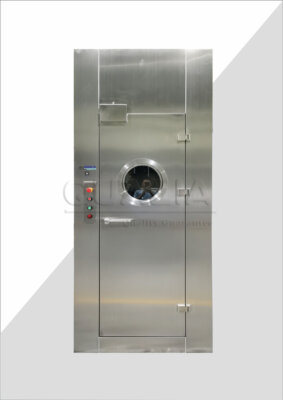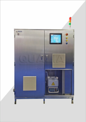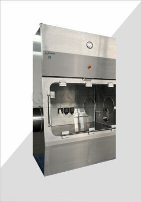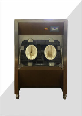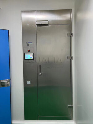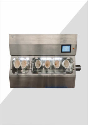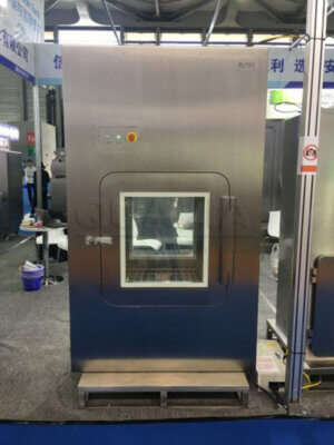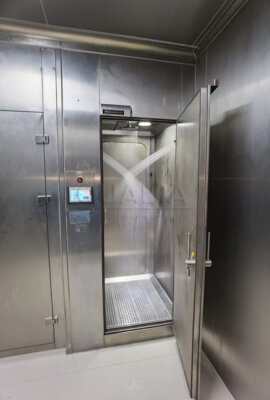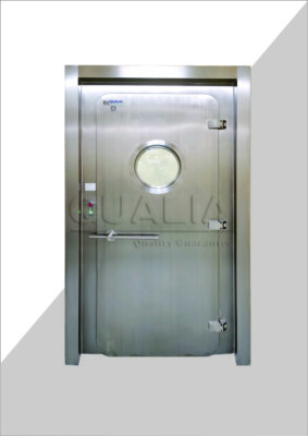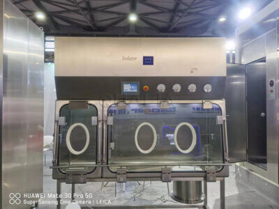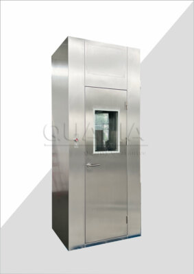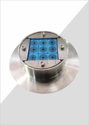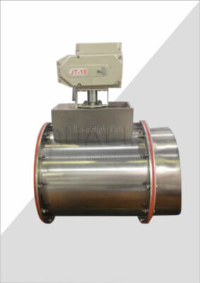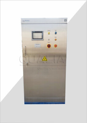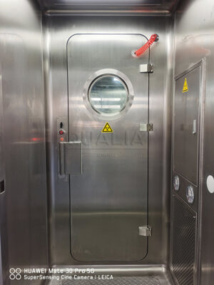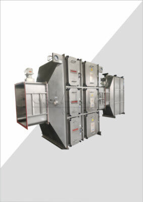
A pneumatic APR door URS defines the door by what it has to do at a specific opening: who passes, how often, which direction the pressure falls, and what the seal has to hold while closed. The deciding variable is the pressure boundary the door sits in, together with the clear-opening geometry and traffic type at that location, because those fix the sealing duty, the opening sequence and the interlock logic before any hardware is selected. An airtight pressure-resistant (APR) door uses an inflatable gasket that expands against the frame when the door is closed, so the compressed-air supply and its loss behavior become part of the specification rather than an installation detail.
Door duty and operating scenarios the URS must define
Start the document with a plain operating description of the door, not a product configuration. Name the use case — personnel passage, equipment transfer, material movement, maintenance access — and state the traffic type and expected frequency, because a door opened several times per shift by gowned staff carrying trays imposes different wear and different sequencing from a door opened only for annual filter changes.
State the clear-opening geometry the process needs, measured against the largest item that must pass: a biosafety cabinet, a transport cart, an isolator section. Clear opening is the usable width and height after the frame, seal and any door leaf intrusion are accounted for, and that distinction is where specifications most often go wrong.
Describe the opening sequence as a sequence. Which door may open first, which must be proven closed, whether a change room requires one leaf at a time, and what the operator sees and does at each step. Then define the surrounding pressure boundary: which side is the higher-pressure side, what cascade the room is designed to hold, and whether the door is part of a containment envelope, an aseptic envelope, or a simple clean-to-less-clean separation. The answer changes which side the seal must work against and which failure direction matters.
Sealing duty belongs here too, and it belongs as a test. Rather than specifying an airtight door, state the project test method, the test boundary the method applies to, and the acceptance criterion the result is measured against. The boundary matters as much as the number: a leakage figure for the door leaf and frame assembly is a different statement from one that includes the wall penetration and the surrounding construction. ISO 14644-4:2022 provides checklists covering cleanroom requirements, design, construction, start-up, performance verification and life-cycle maintenance at a summary level; it frames where a door sits in the design process without prescribing a door technology or a sealing method for your project.
Geometry and boundary interfaces for frame, floor, and surrounding construction
Every APR door is three interfaces as much as it is a door: frame to wall, door to floor, and seal to the surrounding construction. The URS should define each one as a project requirement with a named responsible party, because these are where site work and supplier scope meet.
For the frame, state the wall construction it lands in — modular panel, blockwork, drywall with a sealed liner — along with the panel thickness, the permitted fixing method, and how the joint between frame and wall is to be sealed and finished. A frame detail designed for a 50 mm sandwich panel does not transfer to a masonry opening without rework, and that rework is usually discovered during installation rather than during review.
For the floor, say whether a threshold is acceptable or whether the opening must be flush for carts and trolleys, and state the floor finish and any coving the seal has to meet. A flush opening shifts the sealing duty onto a drop seal or a floor-plane gasket, and it places tolerance demands on the floor flatness that someone must own in the construction schedule.
For the surrounding construction, define how the wall finish terminates at the frame, whether the detail must be cleanable with the facility’s agents, and whether any viewing panel, air transfer device or service penetration occurs within the same wall section. State all of these as project-specific values in your own document; a supplier can offer standard details, but the dimensions and tolerances come from your drawings.
Utilities, controls, alarms, and release behavior by responsible party
| Interface or function | Facility-side requirement to state | Supplier response to require | Loss or release behavior to state |
|---|---|---|---|
| Compressed air | Facility-provided compressed-air conditions and connection boundary | Door-side compressed-air requirement and supplier scope | Required door behavior if compressed air is lost |
| Electrical power | Facility-provided power conditions and connection boundary | Door-side power requirement and supplier scope | Required door behavior if power is lost |
| Wiring | Facility wiring scope | Supplier wiring scope and the interface between them | Any required behavior associated with loss at the stated wiring boundary |
| Building-control connections | Facility building-control scope and connection boundary | Supplier connection scope and required signals | Required behavior if the building-control connection is unavailable |
| Alarms and release functions | Facility-side responsibility for each required alarm or release function | Supplier-side responsibility for each required alarm or release function | Required alarm and release response for the stated utility-loss cases |
Separate facility scope from supplier scope for every utility and signal, and state what the door does when each one is lost. This single discipline prevents the common gap where compressed air is assumed to be supplied, assumed to be dry, and assumed to be on an uninterruptible header, with no one accountable for any of the three.
Compressed air is the defining utility for a pneumatic seal, so the URS should state the facility-provided supply conditions and the physical connection boundary, then require the supplier to state the door-side requirement and what the door does if supply is lost. Power, field wiring and building-control connections need the same treatment: a connection point, a party on each side of it, and a stated behavior when the connection is unavailable.
Release behavior is the part that deserves the most care. State the required emergency egress provision for the opening, the alarm functions the door must raise, and which party supplies each. Where an override, release or return-to-service action follows an alarm, the project’s approved procedure and its designated approver decide whether and when it is taken; the URS names the function and the required response, not the operator’s permission. Interlock logic, signal lists and override handling grow large enough on most projects that they are specified in their own controls document and referenced from the door URS.
Seal materials, cleaning exposure, and maintenance access
Specify the seal elastomer against the actual chemical exposure at that door, not against a general cleanroom description. List the disinfectants and sporicides used on both faces, the vaporized hydrogen peroxide or other gaseous decontamination cycles the door will see, the contact time and the frequency, because the combination of agent, concentration and repetition determines how quickly an inflatable gasket hardens, swells or loses recovery.
State the surface finish and geometry the seal groove must have so that residues do not accumulate where the gasket retracts. Where a door separates areas with different cleaning regimes, say which regime governs the seal, since a gasket wetted from the higher-exposure side sees that chemistry regardless of what the other room uses.
Define maintenance access as a requirement, not an expectation. Say from which side the seal must be replaceable, whether the door may be removed from the frame, how much clearance is available in front of the opening, and whether the replacement can be done without breaching the containment boundary or only under a planned shutdown with the room decontaminated first. Pneumatic seals carry a consumable gasket and an air circuit, which is the trade-off against mechanical-seal doors that use a compression mechanism and no air supply; the choice turns on whether you prefer a dependency on utility air or on mechanical adjustment over the life of the door.
Factory and site evidence tied to traceable acceptance criteria
| Requirement class | Factory evidence to map | Site evidence to map | Acceptance basis | Evidence boundary |
|---|---|---|---|---|
| Specified door function | Evidence identified against the individual function requirement | Evidence identified against the same function requirement at site | Project test method, test boundary, and acceptance criterion | A generic certificate does not establish the specified function |
| Controls, alarms, and release behavior | Evidence identified against each specified control, alarm, or release requirement | Evidence for the required behavior in the installed context | Project test method, test boundary, and acceptance criterion for the named behavior | Evidence for one behavior does not establish the others |
| Utility-loss behavior | Evidence for the stated response to loss of the applicable utility or connection | Evidence for that response at site | Project loss-condition test method, boundary, and acceptance criterion | Normal-operation evidence does not establish the stated loss response |
| Project interfaces | Evidence identified for the supplier-side interface requirement | Evidence for the installed frame, floor, surrounding-construction, utility, wiring, or building-control interface | Project interface check and acceptance criterion | Evidence must identify the interface it covers |
Write the evidence requirement as a mapping: each requirement in the URS has a factory test, a site test, or both, named against that requirement number. The value of the mapping is that a reviewer can open the document and see which specified function each report covers, which is what a document-level certificate cannot show on its own.
Annex 15 of EudraLex Volume 4 treats the URS as a reference across the validation life cycle, with design qualification verifying that the design meets the URS requirements — the exact stages and acceptance criteria stay project-specific. That framing is a reason to write each requirement in a testable form in the first place: a sealing duty with a stated test method and boundary can be verified at design review and again on site, while an unqualified description cannot.
Specify which evidence is produced at the factory and which must be repeated after installation, and say why. Seal performance measured on a test frame tells you about the door assembly; the same measurement in the installed wall tells you about the frame-to-wall joint and the construction around it. Utility-loss behavior should be demonstrated under the loss condition itself, in the installed context, against a method and criterion written for that condition.
Supplier response format for a comparable technical bid
| Bid-response section | Supplier response to provide | Comparison basis |
|---|---|---|
| Door duty and operating scenarios | Offered configuration against the specified use case, traffic type, opening sequence, and surrounding pressure boundary | Alignment with the same stated operating scenarios |
| Geometry and construction interfaces | Response to the clear-opening geometry and the frame, floor, and surrounding-construction boundaries | Alignment with the same geometry and interface boundaries |
| Utilities, controls, alarms, and release behavior | Supplier scope, facility requirements, connection boundaries, and stated behavior during utility loss | Scope split and behavior for the same utilities and functions |
| Seal, cleaning, and maintenance | Offered seal material, cleaning-exposure basis, and maintenance-access response | Alignment with the same project conditions and access requirement |
| Factory and site evidence | Evidence mapped to each requirement and its project test method, boundary, and acceptance criterion | Requirement-level traceability rather than reliance on generic certificates |
Ask every bidder to respond section by section against your URS headings, with the same numbering, so that engineering and procurement are comparing like offers rather than reconciling three different document structures. A free-format technical proposal hides scope gaps; a mirrored response makes them visible in the column where the supplier wrote nothing.
Require each response to state offered scope and excluded scope for every interface, including the compressed-air connection point, the wiring boundary, the frame-to-wall detail and the floor interface. Require the sealing duty response to name the test method, the boundary that method covers and the criterion the supplier will accept, so that two offers can be compared on the same measurement rather than on adjectives.
For the discussion that follows the bids, have ready the room pressure cascade drawing for the opening, the clear-opening dimension driven by your largest transferred item, the traffic type and frequency, the disinfection agents and cycle regime the seal will see, the compressed-air and power conditions available at the wall, and the qualification deliverables your validation plan expects. With those six items defined, a supplier can quote a specific door for a specific opening instead of a catalogue configuration, and QUALIA’s pneumatic-seal APR doors — like any APR door — can be assessed against the boundaries you have already fixed rather than against boundaries proposed after award.
Frequently Asked Questions
Q: What should be resolved before issuing a pneumatic APR door URS for quotation?
A: Define the use case, traffic type, clear opening, opening sequence, surrounding pressure boundary, and key construction interfaces first. If any of these remain undecided, identify them as open project items so suppliers do not base their offers on different assumptions.
Q: Is an “airtight” requirement specific enough for the door seal?
A: No. State the project test method, the boundary being tested, and the acceptance criterion so the sealing duty can be quoted and verified against the same requirement.
Q: How should the URS address loss of compressed air, power, or a building control connection?
A: Specify the required door, alarm, and release response for each relevant loss case. Also assign the facility and supplier connection boundaries so the expected behavior is not left to an unstated scope assumption.
Q: How can procurement compare offers that use different door configurations?
A: Require every supplier to answer the same sections for operating duty, geometry, interfaces, utilities, controls, seal and cleaning conditions, maintenance access, and evidence. Compare each offered response with the stated URS requirement rather than comparing product descriptions alone.
Q: What seal information should be provided when cleaning conditions vary by project?
A: State the expected cleaning exposure and the maintenance access available around the seal. Require the supplier to identify the offered seal material and explain its basis against those project conditions.
Q: When is a generic certificate insufficient as acceptance evidence?
A: A generic certificate is insufficient when it does not identify the specified function, loss response, or project interface it supports. Map factory and site evidence to each individual requirement and its stated test method, boundary, and acceptance criterion.