
A site transferring material between a biosafety boundary and an aseptic boundary cannot plan the interface by picking one piece of equipment and assuming it covers both directions. The project question is whether the transfer route controls release outward, contamination inward, or both at once, and that answer has to be settled before anyone selects a pass box, a VHP chamber, or a dunk tank. Getting this sequence backward is how a transfer point ends up serving neither objective well.
Why one transfer map must reconcile containment and aseptic protection
| Boundary context | Direction to control | Planning consequence |
|---|---|---|
| Biosafety transfer | Release outward | Use a site-specific risk assessment to set proportionate biosafety controls; local rules still apply. |
| Aseptic transfer | Contamination inward | Use suitable transfer controls and, where required, validated transfer disinfection. |
| Combined biosafety and aseptic transfer | Both outward release and inward contamination | Agree the pressure and transfer concept for the project rather than applying one default direction. |
A biosafety transfer route exists to control what leaves a space: material, aerosol, or residue that could carry hazard outward into the surrounding facility or environment. An aseptic transfer route exists to control what enters a space: particulate or microbial contamination that could compromise a product or process. These are not two versions of the same problem. They are opposite-facing controls, and a transfer point that only manages one direction can still fail the other.
Where a project sits entirely within a biosafety context, the transfer concept can reasonably prioritize outward containment, with a proportionate control derived from a site-specific risk assessment, as the WHO Laboratory Biosafety Manual frames it, understanding that local rules and the facility’s own risk assessment still govern the specific proportionate measures chosen. Where a project sits entirely within an aseptic manufacturing context, EU GMP Annex 1 frames the concern differently: transfer controls, validated transfer disinfection, or a suitable transfer system aimed at protecting sterile Grade A/B environments from contamination coming in.
The harder case is the project that has both conditions present at the same boundary — for example, a facility handling a biologically hazardous process intermediate that must also be kept aseptic before it reaches a filling line. In that case neither reference framework, taken alone, resolves the transfer design. The project team has to agree a pressure and transfer concept deliberately, rather than defaulting to whichever direction the first piece of selected equipment happens to control well. A pass box optimized for aseptic ingress protection does not automatically give the project defensible outward containment, and a containment-rated interface does not automatically give the project a validated aseptic transfer. Confirming which objective (or both) governs each specific transfer point is the first design decision, not a detail to resolve after equipment is chosen.
Classify loads by hazard, cleanliness state, packaging, and destination
| Classification factor | Project question | Decision informed |
|---|---|---|
| Hazard | What hazard is associated with the load? | The proportionate containment control for outward release. |
| Cleanliness state | What cleanliness state must be maintained through transfer? | The aseptic protection needed against inward contamination. |
| Packaging state | How is the load packaged during transfer? | Compatibility with the proposed transfer equipment and treatment. |
| Origin and destination | Where does the load start, and where must it be released? | The transfer route and the point at which release evidence is required. |
Before any transfer equipment can be matched to a load, the load itself needs to be described in terms that actually drive equipment selection. Four attributes do most of that work, and they are not interchangeable.
Hazard classification asks what the material could release and into what environment, which informs the proportionate biosafety control the outward-facing side of the transfer needs. This is independent of how clean the material needs to stay — a hazardous load can simultaneously require high cleanliness on the way to a process step, and a clean load can simultaneously carry no containment obligation at all.
Cleanliness state asks what level of contamination control must be preserved through the transfer, which drives the aseptic protection side of the decision: whether a validated transfer disinfection step is required, or whether a less stringent transfer control is sufficient for the material’s eventual use.
Packaging state is a practical constraint that often gets evaluated too late. A double-bagged or rigidly contained item behaves differently in a transfer interface than an open or loosely wrapped one, and the treatment method that suits one packaging state may be incompatible with another — a liquid-sensitive surface treatment is not interchangeable with a method suited to sealed rigid containers, for instance. Packaging state should be confirmed before a treatment method is assumed, not after.
Origin and destination define the actual route: where the load starts, where it must end up, and at what point along that path release evidence becomes necessary. A load moving from a hazardous process area toward a lower-containment area answers to a different release logic than one moving from an uncontrolled area into an aseptic core. Where a single load crosses both kinds of boundary in sequence, its classification needs to be reassessed at each boundary rather than carried forward from the first one.
Getting all four attributes documented for every incoming item, sample, waste stream, and returnable part gives the project a basis for route and equipment selection that doesn’t depend on guessing which factor matters most for a given load.
Separate entry, sample exit, waste, and return paths
Treating “material transfer” as a single generic function at a facility tends to produce a transfer point that is overloaded with incompatible traffic. Entry material, sample exit, waste leaving the space, and returnable parts coming back in are four different path types, and each one carries a different combination of the hazard, cleanliness, and packaging attributes already described.
Entry material moving into a biosafety or aseptic space typically needs the inward-facing control — keeping contamination or unwanted organisms out, or in the containment case, keeping the inbound item itself from degrading the controlled environment it enters. Sample exit reverses that priority: the concern becomes what leaves the controlled space and whether it still carries hazard that needs neutralizing before it reaches an uncontrolled area, a lab bench, or an analytical instrument elsewhere in the facility. Waste streams usually carry the highest hazard classification of any path and the least tolerance for improvisation, since they are typically the path most likely to carry contamination or hazardous residue at the point of exit. Returnable parts — tools, components, or reusable containers moving back into a controlled space after work outside it — need their own treatment logic, because a part that previously sat in an uncontrolled environment cannot be assumed clean simply because it was clean when it originally left.
Where a facility collapses several of these paths into one shared interface, the transfer point has to be designed for the most demanding combination of attributes among all the path types using it, which can over-specify the control needed for the easier paths and create scheduling conflict between them. Where the project separates these paths physically or procedurally, each one can be matched to a transfer method proportionate to its own hazard and cleanliness profile, and the equipment at each interface can be selected without compromise for traffic it was never meant to carry. Mapping which path types actually exist at a facility, and whether any of them have been combined for convenience rather than for a documented reason, is a necessary step before equipment selection, independent of what equipment is eventually chosen.
Match pass boxes, VHP chambers, dunk tanks, and closed interfaces to the load
Once loads are classified and paths are separated, the project can match specific transfer equipment types to specific transfer needs — but the match depends on load compatibility and the treatment and evidence that load requires, not on which equipment type is most familiar to the project team.
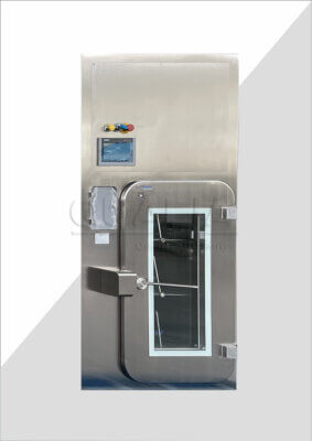
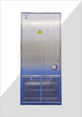
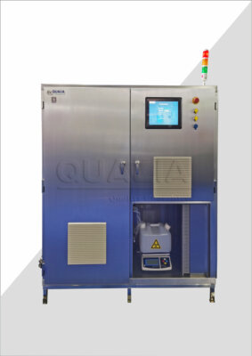
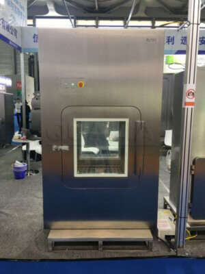
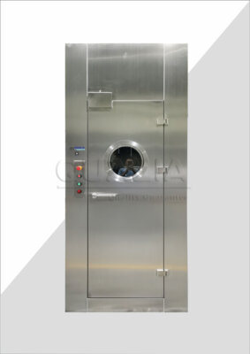
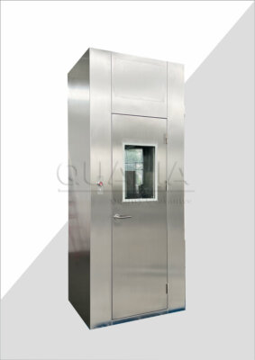
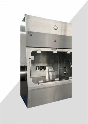
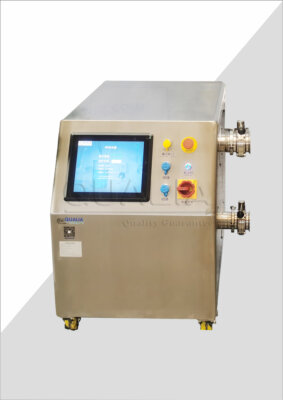
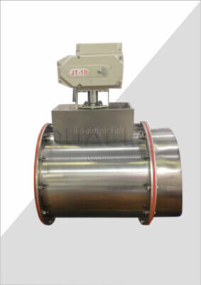
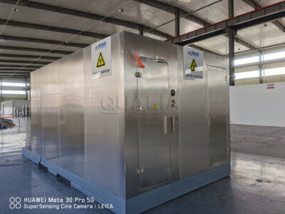
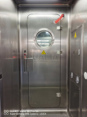
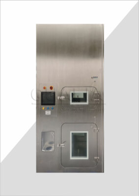
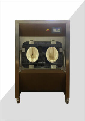
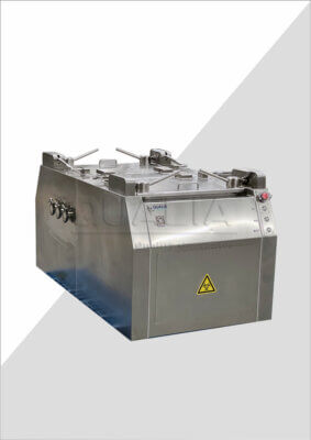
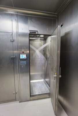
A pass box provides a physically separated transfer interface between two environments, typically with interlocked doors that prevent simultaneous opening on both sides. Within that general category, a Biosafety Pass Box and a VHP Pass Box serve different combinations of hazard and cleanliness need: one is configured around the interlock and containment logic a biosafety boundary requires, while the other incorporates a vapor-phase hydrogen peroxide treatment cycle suited to loads that need a validated decontamination step as part of transfer, which is relevant where the aseptic side of a combined boundary requires documented transfer disinfection rather than a passive interlocked pass-through alone.
A dunk tank handles a different packaging reality — loads that can tolerate, or require, immersion in a liquid disinfectant as they cross the boundary, which suits rigid, liquid-tolerant containers but is not a fit for materials or packaging that a liquid treatment would damage or fail to penetrate.
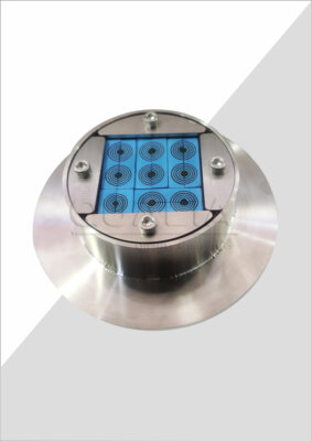
A closed transfer interface, more broadly, is suited to loads where the packaging itself maintains the separation between environments through a docking or continuous-liner mechanism, avoiding an open transfer step altogether; this becomes relevant where the load’s own hazard or cleanliness requirement makes any open-air moment in the transfer process unacceptable.
None of these equipment types is a universal answer, and selecting one typically forecloses the others for that interface. A dunk tank cannot accommodate a load whose packaging would be compromised by immersion; a VHP-based treatment is not suited to a load that is incompatible with the treatment chemistry or moisture exposure; an interlocked pass box without a treatment cycle does not, on its own, provide a validated transfer disinfection step where one is required. The decision should follow from the load classification and path type already established, with the project confirming which treatment and evidence that specific load needs before the equipment category is chosen, rather than selecting equipment first and asking whether the load fits it afterward.
Define interlocks, treatment cycles, release evidence, and exception handling
| Control element | Project-specific definition | Decision boundary |
|---|---|---|
| Interlocks | Required interlock behavior for the agreed pressure and transfer concept. | The transfer sequence must remain within the agreed boundary concept. |
| Treatment cycle | Load-compatible treatment and the cycle parameters to be validated for the project. | There is no universal VHP cycle recipe; use validated transfer disinfection where required. |
| Release evidence | Evidence that must be available before a transferred load is released. | Release depends on the defined evidence rather than completion of a transfer step alone. |
| Exception handling | The action when an interlock, treatment cycle, or release condition is not satisfied. | An unresolved exception does not become a normal release path. |
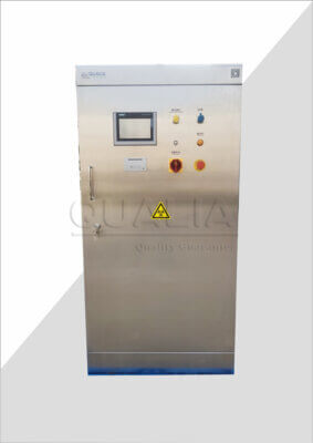
Selecting the right equipment category is necessary but not sufficient. Each transfer interface also needs its control logic defined in project-specific terms, because none of these elements has a universal default setting that applies across projects.
Interlock behavior has to match the pressure and transfer concept the project agreed earlier. An interlock that prevents both doors of a pass box from opening simultaneously protects the separation between two environments, but the specific sequencing — which door can open under which condition, and what happens if the sequence is interrupted — needs to be defined against the project’s actual boundary concept, not assumed from the equipment’s default factory logic.
Treatment cycles are where generic assumptions cause the most difficulty. EU GMP Annex 1 is explicit that there is no universal VHP cycle recipe; validated transfer disinfection has to be developed and confirmed for the specific load, packaging, and chamber involved. A cycle validated for one load type does not transfer automatically to a different packaging state or material, even within the same piece of equipment. The project needs to identify, for each load type crossing a treatment-based interface, what cycle parameters apply and how those parameters will be validated.
Release evidence is the documentation or verification step that determines whether a transferred load is actually permitted to proceed, and it should be defined independently of the mechanical completion of a transfer step. A cycle finishing, or a door closing, is not the same as release being authorized; the project needs to specify what evidence — cycle confirmation, visual check, documentation — constitutes release for each path and load type.
Exception handling closes the loop: what happens when an interlock fails to engage, a treatment cycle does not complete as validated, or release evidence is incomplete. An unresolved exception cannot be allowed to become a normal, repeatable release path by default, which means the project needs a defined action — hold, reprocess, escalate — for each failure mode rather than leaving it to be improvised at the point of failure. This is also where facility-specific information, such as the load types and treatment requirements the project has already classified, becomes the basis for a configuration or quotation review of the specific transfer equipment needed at each interface.
Set capacity, ownership, and acceptance checks before design freeze
| Capacity factor | Project-specific input | Capacity implication |
|---|---|---|
| Staging space | Space needed to stage loads around transfer. | Staging demand is part of the capacity plan even when the load fits the chamber. |
| Peak batch mix | The combination of load types expected at peak demand. | Peak handling depends on the batch mix as well as chamber volume. |
| Cycle reset | The reset needed before the next transfer cycle. | Reset affects when the equipment is available for another load. |
| Exception handling | The handling path when normal treatment or release cannot be completed. | Exceptions can occupy transfer capacity and must be included in the plan. |
Nominal chamber volume is the easiest capacity figure to quote and the least complete one to design around. A transfer interface’s actual throughput depends on several operating conditions that chamber volume alone does not capture, and all of them need to be estimated before the design is frozen, not discovered afterward.
Staging space is needed around the transfer point regardless of whether the load fits inside the chamber, because loads arriving for transfer and loads awaiting release after transfer both need somewhere to wait without blocking the interface or mixing with unrelated traffic. A chamber sized correctly for the load itself can still create a bottleneck if no provision exists for staging on either side.
Peak batch mix matters because a facility’s transfer demand rarely consists of a single repeating load type; the combination of load types expected at a busy period determines how much of the chamber’s nominal capacity is actually usable at once, since incompatible loads generally cannot share a cycle even if they would physically fit together.
Cycle reset — the time and procedure needed before the equipment is ready for the next load — determines how often the chamber is actually available, independent of how large it is. A larger chamber with a long reset can offer less practical throughput than a smaller one with a short reset, depending on the batch mix the project expects.
Exception handling, again, has a capacity consequence: a load held for reprocessing or escalation occupies the interface or its staging space for longer than a normal transfer, and a capacity plan that assumes every load proceeds on the first attempt will under-provision for the exception cases the control logic has already acknowledged will occur.
Where the project’s priority is primarily outward containment, staging and exception handling tend to dominate the capacity conversation, since failed or incomplete treatment cycles cannot be allowed to exit. Where the project’s priority is primarily aseptic protection, peak batch mix and cycle reset tend to dominate, since contamination risk accumulates with every reopening of the interface. Before the design is frozen, the project should confirm which of these factors governs its specific transfer points, who owns the acceptance check for each interface, and what evidence — drawn from the load classification, path separation, and control definitions already established — will be reviewed when the configuration is finalized with the equipment supplier.
Frequently Asked Questions
Q: What information should be fixed before a material transfer route is selected?
A: Build a load register covering every incoming item, sample, waste stream, and returnable part. For each load, record its origin, destination, hazard, cleanliness state, packaging state, required treatment, and the evidence needed before release.
Q: Can one default pressure direction cover a boundary that requires both biosafety and aseptic control?
A: No. The project must agree a pressure and transfer concept that addresses both outward release and inward contamination, using the site-specific risk assessment and applicable local requirements to set the boundary conditions.
Q: Should incoming materials, outgoing samples, waste, and returnable parts share the same transfer route?
A: Not automatically. Map each path separately because its origin, destination, packaging, hazard, cleanliness state, and release point may differ; then check whether combining paths would create a conflict in treatment or release conditions.
Q: How should a team compare a pass box, VHP chamber, dunk tank, and closed transfer interface?
A: Compare them against each load’s packaging compatibility, required treatment, transfer direction, and release evidence. A route should remain provisional until those project-specific checks show that the load and the proposed treatment can be handled together.
Q: When is a transferred load ready for release?
A: It is ready only when the evidence defined for that route is available and the required interlock and treatment conditions have been satisfied. If any condition fails, use the planned exception path rather than treating physical transfer completion as approval to release.
Q: Why can a chamber that fits the largest load still become a bottleneck?
A: Physical fit does not establish usable throughput. Check staging space, the peak mix of load types, cycle reset, and the time and space consumed by exceptions before accepting the capacity plan.