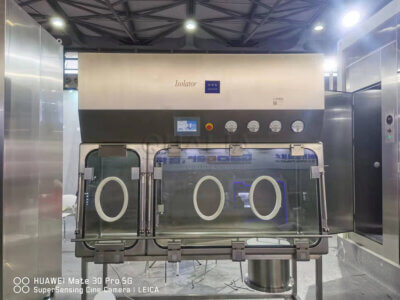
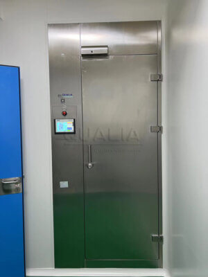
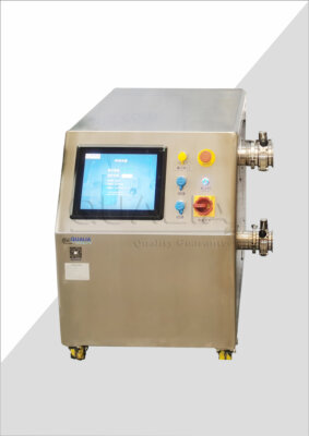
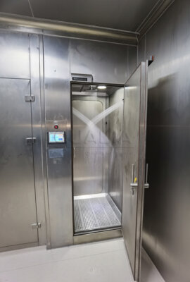
Fixed VHP distribution into a chamber, isolator, or room can route through the facility’s existing air handling or through piping dedicated to the decontamination cycle alone. The choice affects how the cycle is sequenced, what fails when a component fails, and how many interfaces the project team must qualify before the system is accepted. Project owners, engineering teams, and validation groups weighing this decision need to separate the containment question from the hardware question before either architecture can be compared fairly.
The Choice Depends on the Containment and Operating Boundary
The first judgment is not mechanical but architectural: what is the containment or product-protection boundary that the VHP cycle must respect, and can the air-handling path that serves that boundary be isolated and controlled for decontamination without exposing untreated areas to the space being treated, or the reverse? This question precedes any comparison of hardware because it determines which architectures are even eligible for the project.
Where the governing boundary is a shared air-handling system serving multiple rooms or process zones, the viability of routing VHP through that system depends on whether dampers, fans, and ductwork can be positioned into a decontamination-isolated state reliably enough that adjoining areas remain untreated or unexposed throughout the cycle. If that isolation cannot be demonstrated for the specific system configuration, shared-air routing is not a candidate regardless of its other advantages. Where the boundary is narrower, such as a single isolator or an enclosure with its own dedicated air path, the isolation question is simpler to resolve but does not disappear; the enclosure’s own dampers, filters, and return paths still need a defined decontamination state distinct from its normal operating state.
This is also the point at which the project must decide whether the governing objective is aseptic product protection, hazardous-material or biosafety containment, or both in different zones of the same facility. A VHP cycle serving an aseptic isolator is validated against different acceptance logic than one serving a BSL-level containment space or an OEB-rated enclosure, and the distribution architecture has to be evaluated against whichever objective actually governs the space in question, not against the equipment’s general technical description.
Once the containment and operating boundary is defined, the practical comparison becomes whether to lean on the facility’s air handling to carry the gas, or to install piping whose only function is VHP distribution. Both routes are explored below, but neither answers the boundary question on its own; the boundary question has to be settled first because it determines which hardware interfaces will even be in scope for the design review.
HVAC-Assisted Distribution: Integration Advantages and Control Dependencies
Routing VHP through existing air-handling infrastructure uses dampers, fans, and ductwork that the room already has, which can reduce the amount of separate distribution hardware the project needs to design, install, and later maintain. This is the architecture’s core appeal: it treats VHP distribution as a mode of an existing system rather than as a new system layered on top of it.
That appeal comes with a dependency that has to be evaluated on its own terms. Once VHP delivery rides on HVAC infrastructure, the cycle’s sequencing becomes tied to that infrastructure’s behavior: damper positions, fan states, and leakage control all become part of the decontamination cycle’s control logic, not just part of normal ventilation control. Where the HVAC system is highly available and its damper and fan states are tightly monitored, this dependency is manageable because the cycle can rely on known, verifiable states at each step. Where HVAC availability is intermittent, shared across multiple uses, or subject to maintenance windows that the decontamination schedule does not control, the dependency becomes a scheduling and reliability constraint on the VHP cycle itself, not merely a convenience trade-off.
Leakage control deserves particular attention under this architecture because the same ductwork that carries conditioned air during normal operation must also hold the decontamination state without allowing gas to migrate into adjoining zones. The damper and seal performance required for routine ventilation is not automatically sufficient for a decontamination hold state, and the project team needs to confirm what leakage control the specific HVAC hardware provides under the sealed, non-ventilating condition the cycle requires, as distinct from its leakage performance under normal airflow.
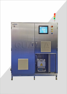
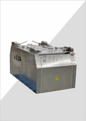
The configuration question that follows from this is how VHP generation and delivery hardware, such as a Generator nadtlenku wodoru VHP, interfaces with the HVAC system’s control points. The generator’s role is to produce and deliver the gas; whether that delivery can be coordinated with damper and fan sequencing to the degree the project needs is a question the HVAC and controls design must answer together, and it is the kind of project-specific detail that enters a configuration or quotation discussion once the containment boundary and the HVAC system’s actual capabilities are both known.
Dedicated Piping: Routing Flexibility and Additional Hardware Interfaces
Dedicated piping separates the VHP injection path from the room’s normal ventilation entirely, which means the gas travels through hardware installed specifically for the decontamination function rather than through infrastructure that also does other work. This separation gives the project more freedom in where injection and return points are located, because the routing is not constrained by where the existing ductwork happens to run.
That flexibility is gained by adding hardware that a shared-air approach would not need: penetrations through walls or enclosures, valves to control and isolate the dedicated path, and balancing work to confirm that gas distribution across the piping network is even enough for the cycle to be meaningful. Each penetration is a point the containment or aseptic boundary has to account for, each valve is a component with its own failure mode and maintenance requirement, and balancing is not a one-time installation step but an ongoing characteristic of the piping network that can shift if the room, load, or piping configuration changes.
Where the governing boundary is tightly defined and shared air handling cannot be isolated to the degree the cycle requires, dedicated piping avoids that isolation problem by not touching the shared system at all. Where the room’s layout or process equipment makes additional penetrations and valve placements difficult to accommodate, or where the maintenance program is not resourced to inspect and service an added set of valves and balancing points on a recurring basis, the hardware burden of dedicated piping becomes the more significant design constraint, even though it solves the isolation question cleanly.
The routing flexibility that dedicated piping offers is most valuable where injection points need to be placed close to specific load items or geometries that shared ductwork cannot reach efficiently. In those cases, the additional valves and penetrations are the cost of achieving injection placement that a shared-air path could not provide. Whether that trade is worthwhile depends on how sensitive the room’s load and geometry are to injection placement, which is a question the room’s qualification work, not the architecture choice itself, will ultimately answer.
Failure States, Isolation Logic and Aeration Paths to Compare
| Punkt odniesienia | HVAC-assisted distribution | Dedicated piping | Design-review decision boundary |
|---|---|---|---|
| Containment and isolation | Shared air handling must be isolatable and controllable for decontamination without exposing untreated areas. | Injection routing can be separated from normal ventilation, while the containment boundary still governs the selection. | Establish the containment boundary and decide whether shared air handling can be isolated and controlled for the cycle. |
| Routing and hardware | May reduce separate distribution hardware, but cycle sequencing is tied to dampers and fans. | Adds penetrations, valves and balancing points. | Map the injection and return routes and compare the resulting interfaces. |
| Aeration control | Aeration sequencing depends on the HVAC path and HVAC availability. | The aeration path remains project-specific and must be mapped with the selected routing. | Map the aeration path before selecting the architecture. |
| Failure states and upkeep | Leakage control and HVAC availability are explicit dependencies to assess. | Added valves, balancing and maintenance points create additional interfaces to assess. | Map failure states and controls ownership for the selected architecture. |
| Performance evidence | Architecture selection alone does not prove uniform distribution or cycle efficacy. | Architecture selection alone does not prove uniform distribution or cycle efficacy. | Develop and qualify the actual room and load; exact acceptance values remain project-specific. |
Comparing the two architectures directly requires looking past their general advantages and into what happens when a component fails, how isolation is actually enforced, and where the aeration path runs once the cycle’s active phase ends. These three elements interact differently depending on which architecture is chosen, and the design review needs to resolve each one rather than treating “HVAC-assisted” or “dedicated piping” as a single decision point.
Failure states differ in kind between the two architectures. In an HVAC-assisted system, a failure in a damper, fan, or the HVAC system’s availability directly affects the decontamination cycle, because the same components that fail also carry the gas. In a dedicated piping system, failures occur in valves or balancing elements that exist only for the VHP function, which means a failure there does not also disrupt normal ventilation, but it does mean the dedicated system has its own distinct set of failure points that the shared-air approach does not introduce.
Isolation logic is the mechanism that prevents the cycle from exposing untreated areas, and it has to be verified for the specific hardware in use rather than assumed from the architecture’s category. An HVAC-assisted system’s isolation logic rests on damper and fan positioning achieving and holding a sealed state; a dedicated system’s isolation logic rests on valves at the piping boundary achieving and holding their closed or open state as the cycle requires. Both depend on position feedback and monitoring that the project must specify, not on the architecture type alone.
Aeration paths, the route by which residual gas is removed once the active cycle ends, follow the same logic as injection and return paths and must be mapped with the same attention to sensor placement and controls ownership. An HVAC-assisted aeration path depends on the HVAC system returning to a ventilating state on command and at a rate the cycle’s aeration requirement assumes; a dedicated-piping aeration path depends on the dedicated system’s own vent or exhaust points and the valves that control them. Neither path is self-evidently faster or more reliable than the other; both require monitoring that confirms the aeration state has actually been reached, not merely commanded.
Sensor placement and controls ownership tie all three elements together. Where control of the dampers, fans, or valves involved in the cycle sits with a different system or a different responsible party than the VHP generation and delivery equipment, the project needs a clear definition of which controls platform commands which component during injection, hold, and aeration, and how failure of any single element is detected and reported.
Selection Evidence the Design Review Must Resolve
| Evidence or project input | Wykorzystanie decyzji | Granica dowodów |
|---|---|---|
| ISO 14644-4:2022 cleanroom framework | Structure design, construction, start-up, verification and life-cycle maintenance checks. | It does not prescribe a specific technology, process or contractual delivery method. |
| EU GMP Annex 1 contamination control strategy | Identify critical control points and evaluate design, technical, procedural and monitoring controls. | It is written for EU sterile manufacture; use elsewhere must be documented and justified. |
| Annex 15 URS and design qualification framework | Use the user requirements specification as a life-cycle reference and verify that the design complies with it. | Exact qualification stages and acceptance criteria remain project-specific. |
| Injection, return and aeration paths, sensor locations, failure states and controls ownership | Resolve the architecture-specific routing, monitoring and control basis before selection. | These mapped inputs do not by themselves prove uniform distribution or cycle efficacy. |
| Actual room- and load-specific development and qualification | Establish performance for the room and load that will be used. | Neither distribution route provides this evidence by architecture choice alone. |
Neither architecture, by itself, proves that the gas will distribute uniformly through the room or load, or that the cycle will achieve the efficacy the project requires. Architecture selection establishes the routing, isolation, and control framework; it does not substitute for qualifying the actual room and load that will be treated once the equipment is installed.
The design review should treat this as a sequence: first, define the containment or product-protection boundary that governs the space, drawing on the kind of facility-wide contamination control thinking that Załącznik 1 do GMP UE sets out for sterile manufacturing contexts, or the equivalent containment logic where the governing objective is biosafety or hazardous-material protection rather than sterility. Second, use that boundary to decide which architecture, or combination, can achieve the isolation the cycle requires, informed by the design, construction, and verification framework that ISO 14644-4 provides for cleanroom-level systems generally, recognizing that this framework does not prescribe a specific distribution technology or contractual delivery method. Third, capture the injection, return, and aeration routing; sensor locations; failure states; and controls ownership as explicit user requirements, since Załącznik 15 treats the URS as the reference against which design qualification confirms the installed system actually complies.
None of these evidence sources, individually or together, replaces qualifying the room and load as installed. The mapped routing and controls basis tells the project team what the system is supposed to do and how it is supposed to fail safely; it does not tell them whether the gas concentration reaches every surface the process requires or whether the cycle time achieves the exposure the application needs. That evidence comes only from qualification work performed against the actual room, load, and installed hardware.
Where the project’s facility interface questions extend into how HVAC scope and process air-handling scope are divided between the facility and the equipment supplier, that division is a related but separate coordination question from the VHP distribution architecture itself, and it benefits from being resolved early so that the controls ownership question above has a clear answer before FAT or SAT planning begins.
Często zadawane pytania
Q: When is HVAC-assisted VHP distribution a practical option?
A: It is practical when the shared air-handling system can be isolated and controlled for the decontamination cycle without exposing untreated areas. Confirm the containment boundary, damper and fan sequencing, leakage control, aeration path, and HVAC availability before selecting this route.
Q: What project information should be prepared before comparing the two distribution routes?
A: Prepare mapped injection, return, and aeration paths together with proposed sensor locations, failure states, and controls ownership. The design review should also identify the actual room and load that will require development and qualification.
Q: Does dedicated piping eliminate the need to coordinate with the ventilation system?
A: No. Dedicated piping can separate VHP injection routing from normal ventilation, but the aeration path remains project-specific. The review must also account for the added penetrations, valves, balancing points, and maintenance interfaces.
Q: How should controls ownership be divided for the selected architecture?
A: Assign clear ownership for the controls governing each mapped injection, return, and aeration path and for the response to identified failure states. For an HVAC-assisted route, this includes the dependencies on dampers, fans, leakage control, and HVAC availability; for dedicated piping, it includes the added valves and balancing points.
Q: Does selecting HVAC-assisted or dedicated distribution prove that the cycle will work uniformly?
A: No. Architecture selection alone does not prove uniform VHP distribution or cycle efficacy. The actual room and load require development and qualification, with user requirements and project-specific acceptance criteria defined for that application.