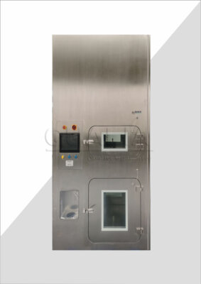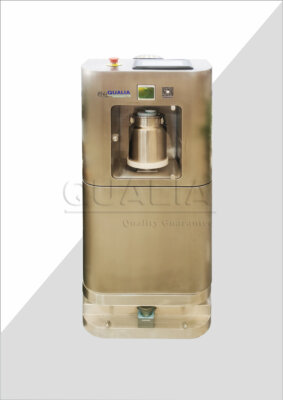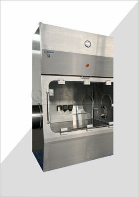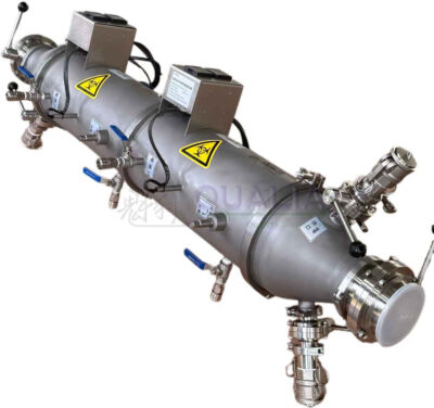
When a barrier system runs negative to protect operators from hazardous material, does that same pressure state still protect the product inside it from the room? The two questions sound related, but they rest on different physics and different evidence, and a project that answers only one of them has not finished defining its protection strategy.
The two protection objectives and where they can conflict
| Protection objective | What is protected | Supported pressure or airflow condition | Decision boundary |
|---|---|---|---|
| Negative-pressure containment | Operators and the surrounding environment | Inward containment airflow and a defined leakage direction for hazardous material | A single room differential does not define the full hierarchy across the room, barrier, transfer interface, and exhaust path |
| Aseptic product protection | Exposed product | A controlled clean environment around the exposed product | Negative pressure alone does not establish aseptic protection |
A negative-pressure barrier establishes a leakage direction: air moves from the surrounding space toward the controlled volume, so that hazardous material inside does not reach operators or the environment outside. That is a containment objective, and it is satisfied when inward airflow is sustained and the leakage direction stays consistent under the conditions the project defines. Aseptic product protection asks a different question: whether the environment immediately around exposed product stays clean enough, regardless of which direction air leaks relative to the room. These two objectives can share a barrier and still pull in different directions. A pressure state that reliably pulls air inward to protect operators does not by itself say anything about whether that inward air is itself clean, or whether the barrier’s internal airflow pattern protects the product zone from the air it draws in.
Where a process involves material that is both hazardous to the operator and intended to remain sterile, the project has to decide how a single barrier, or a combination of barrier and room, satisfies both objectives at once, rather than assuming that solving containment solves product protection as a byproduct. This is not a matter of degree; it is a matter of what each pressure relationship is actually doing. A room that is negative to its surroundings tells the reader about the room’s relationship to the outside. It says nothing about the relationship between the barrier interior and the product-contact zone inside it, which is where aseptic protection actually has to hold.
The practical consequence is that a specification written only in containment terms, or only in aseptic terms, leaves the other objective undefined. A buyer reviewing a barrier system for a process that carries both a hazard profile and a sterility requirement should expect the project documentation to state both objectives explicitly and show how the equipment’s pressure and airflow design addresses each one, rather than treating one as a stand-in for the other.
Define pressure zones around the room, barrier, transfer interface, and exhaust
| Zone or interface | Relationship to establish | Project-specific question |
|---|---|---|
| Room | Room pressure relationship and intended airflow direction at the containment boundary | Which room differential and leakage direction define the intended containment state? |
| Barrier | Barrier pressure relationship to the room and the controlled clean environment around exposed product | How does the barrier pressure state support both containment and aseptic protection? |
| Transfer interface | Intended leakage direction when the transfer opening is in use | What direction must leakage take at the transfer interface for the selected process and hazard? |
| Exhaust path | Pressure relationship through the HEPA exhaust path | How does the exhaust path support the defined hierarchy and intended leakage direction? |
A single room differential cannot describe a system that has to satisfy both containment and aseptic objectives, because the room is only one of several places where a pressure relationship has to be defined on purpose. The room sets the relationship between the containment boundary and the surrounding facility. The barrier sets a second relationship: how the space immediately around the product compares to the room it sits inside, and whether that relationship supports the clean environment the product needs as well as the containment direction the hazard needs. The transfer interface is a third zone, and arguably the one most often under-specified, because its pressure behavior only matters at the moment it is open, which is a different condition from the barrier’s closed-state behavior. The exhaust path is the fourth zone: the HEPA exhaust route has its own pressure relationship, and it has to reinforce the same leakage direction that the room and barrier establish, not work against it.
Each of these four zones needs its own stated relationship and its own project-specific answer, because a design that is correct at the room level can still leave the transfer interface or exhaust path undefined. Where the barrier is a closed system with minimal manual transfer activity, the transfer interface question may be simpler to resolve; where the process requires frequent material movement in and out of the controlled zone, the transfer interface becomes a point where the intended leakage direction has to be verified independently of how the room and barrier behave when sealed. A buyer evaluating equipment should expect the pressure hierarchy to be documented zone by zone, not expressed as a single number that is assumed to describe the whole system.
Trace leakage direction during normal work and credible disturbances
| Operating condition | Leakage path to trace | Decision boundary |
|---|---|---|
| Normal closed work | Room, barrier, controlled product zone, transfer interface, and exhaust path | Closed-state behavior does not by itself establish behavior during interventions, openings, or airflow disruption |
| Glove intervention | Glove intervention point in relation to the barrier pressure state and exhaust path | Confirm the intended leakage direction for the actual intervention condition |
| Transfer opening | Open transfer interface in relation to the room, barrier, and exhaust path | Closed-transfer evidence does not establish leakage direction while the opening is in use |
| Pressure or airflow disruption | The affected pressure zones and exhaust path | Identify whether product protection, containment, or both are at risk before defining the response |
Knowing the intended leakage direction when everything is closed and quiet is a necessary starting point, but it is not the same as knowing what happens when the system is actually in use. Glove interventions change the local pressure relationship at the point of intervention, and that local change can matter even when the barrier’s overall pressure state has not shifted. A transfer interface that is correctly negative when sealed tells the reader nothing about its leakage direction while the opening is actually in use, because opening the interface changes the airflow path itself, not just a number on a gauge.
The same logic applies to disturbances that are not part of routine operation: a change in facility air balance, a door opening elsewhere in the room, or an exhaust-path disruption can each shift the pressure relationship in ways that closed-state testing does not reveal. Tracing the leakage path under each of these conditions separately, rather than assuming that a single verified state covers all of them, is what connects the design intent from the previous section to the operating reality the system will face. Where the process involves infrequent interventions and a closed-transfer strategy, the number of conditions that need separate tracing is smaller; where interventions and transfers are a routine part of the workflow, the project has to trace leakage direction across each of those conditions individually, because each one presents a distinct opportunity for the intended direction to reverse or weaken.
This is also where the distinction between containment risk and product-protection risk becomes concrete. A disturbance that threatens containment and a disturbance that threatens the product’s clean environment are not always the same event, and a project should be able to say, for each credible disturbance, which protection objective is actually at stake.
Select isolator or cRABS controls for the process and hazard
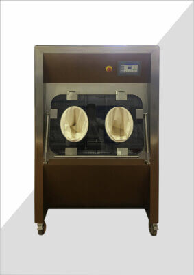
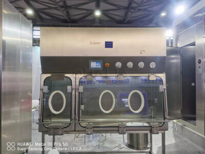
Isolator and cRABS platforms both use barrier separation, but they distribute leakage control, airflow management, and intervention access differently, and the choice between them has to follow from the process and hazard profile rather than from a general preference for one barrier type over the other. An isolator typically offers a more fully sealed boundary with its own internal airflow and decontamination strategy, which supports situations where the process requires a high degree of separation between the operator environment and the controlled zone across both containment and product-protection objectives. A cRABS keeps a closer relationship to the surrounding room’s air handling, which can simplify integration where the facility’s background environment is already controlled to a level that supports the product-protection objective, but it also means the barrier’s performance is more dependent on the room’s own pressure and airflow behavior.
Glove interventions are a design variable in either case, not just an operational detail: where the process requires frequent or prolonged intervention, the selection has to account for how glove ports affect both containment leakage paths and the clean environment around the product during and after each intervention. Transfer openings raise a parallel question, because each barrier type handles material transfer differently, and the transfer strategy chosen has to support the leakage direction the hazard requires while still protecting the product from whatever enters through that opening. Decontamination strategy ties these together: a barrier’s internal decontamination approach has to reach the surfaces that matter for both objectives, not just the surfaces relevant to one of them.
The selection decision also depends on how HEPA supply and exhaust are arranged within the barrier, because supply air quality and its interaction with the containment exhaust path jointly determine whether the barrier can hold both leakage direction and clean-zone performance under the conditions the process actually creates. A project team working through this decision benefits from treating isolator and cRABS not as interchangeable barrier options but as different distributions of these same variables, matched against the specific process and hazard rather than selected by default.
Build alarms, safe states, and operator actions around each failure
| Alarm-response element | Question the response must answer | Decision consequence |
|---|---|---|
| Protection state at risk | Is product protection, containment, or both at risk? | Define the affected state before selecting the safe response |
| Operations to stop | Which operation stops when that state is at risk? | Tie the alarm to an explicit project-specific safe state |
| Evidence before restart | What evidence shows that the affected protection state has been recovered? | Restart only after the defined recovery evidence is available |
An alarm that only indicates a pressure deviation leaves the operator without the information needed to respond correctly, because the same deviation can threaten containment, product protection, or both, and the correct response differs depending on which is at risk. Defining the alarm response starts with identifying which protection state the specific alarm condition actually threatens: a transfer-interface deviation during an open transfer may threaten containment leakage direction without touching the product zone, while a barrier airflow disruption during an intervention may threaten the product’s clean environment without creating a containment failure. Treating every alarm as a generic “pressure excursion” collapses this distinction and can lead to a response that addresses the wrong risk, or addresses both when only one needed attention.
Once the affected protection state is identified, the response has to specify which operation stops. This is a project-specific decision tied to the actual workflow: a process with continuous material flow through a transfer interface needs a defined stopping point that does not leave material mid-transfer in an undefined pressure state, while a closed-barrier process with no active transfer may have a simpler stopping condition. The safe state is not generic; it has to be built around what the equipment and process are actually doing at the moment of the alarm.
The final element is restart evidence: what has to be confirmed before operations resume. This evidence should correspond to the protection state that was at risk, not to the alarm condition in general. A containment-related alarm calls for evidence that the leakage direction has been restored; a product-protection alarm calls for evidence that the clean environment around the product has been reestablished. Where both states were at risk, both forms of evidence are needed before restart, and neither substitutes for the other. A buyer defining alarm philosophy with a supplier should expect this chain, from affected state to stopped operation to restart evidence, to be worked out condition by condition rather than left as a single generic alarm-and-reset procedure.
Demonstrate both product protection and containment before release
| Evidence area | What it can support | What it does not establish by itself |
|---|---|---|
| Critical pressure monitoring, records, and alarms | Evidence that the defined pressure differences were monitored and that disruptions were addressed | Complete performance across leakage paths, transfer openings, and interventions |
| Barrier leak testing | Evidence for the tested leak condition of the barrier | Aseptic product protection and containment across every operating condition |
| HEPA supply and exhaust integrity | Evidence for the tested condition of the supply and exhaust filtration paths | The intended leakage direction across all pressure zones and interfaces |
| Decontamination-cycle evidence | Evidence for the project-specific decontamination strategy and cycle | Pressure control, leakage direction, or operator protection |
| Product-protection evidence | Evidence addressing the controlled clean environment around exposed product | Containment of hazardous material |
| Operator-protection evidence | Evidence addressing containment for operators and surroundings | Aseptic protection of exposed product |
Release evidence has to be assembled from distinct sources, each of which supports a specific claim and none of which substitutes for the others. Critical pressure monitoring, records, and alarms, the kind of evidence referenced in EU GMP Annex 1 for sterile manufacturing, demonstrate that defined pressure differences were tracked and that disruptions were addressed as they occurred; this evidence does not by itself demonstrate performance across every leakage path, transfer opening, and intervention the system will encounter, since monitoring records show what happened under the conditions monitored, not every condition the process will create. The BMBL’s treatment of sustained inward airflow and entry monitoring for BSL-3 work reflects a parallel logic on the containment side: the evidence available is advisory and specific to the conditions evaluated, and it does not establish a universal numeric pressure standard that applies regardless of project circumstances.
Barrier leak testing demonstrates the leak condition of the barrier as tested, a form of evidence relevant to the separative-device requirements described in ISO 14644-7, but a leak test result does not extend automatically to aseptic protection or containment performance across every operating condition the barrier will see in service. HEPA supply and exhaust integrity testing demonstrates the tested condition of those specific filtration paths; it does not, by itself, confirm the intended leakage direction across every pressure zone and interface the system includes. Decontamination-cycle evidence addresses the specific decontamination strategy and cycle used; it does not speak to pressure control, leakage direction, or operator protection, which are governed by different mechanisms entirely.
Product-protection evidence and operator-protection evidence are similarly distinct from each other: evidence addressing the controlled clean environment around exposed product does not establish containment of hazardous material, and evidence addressing containment for operators and surroundings does not establish aseptic protection of the product. Where a project requires both objectives from the same equipment, release documentation should keep these evidence types separate and explicit rather than letting one stand in for the other. This is the kind of project information that enters a configuration or quotation review with Qualia: stating both objectives, the process conditions behind them, and the evidence already available allows the configuration discussion to address what still needs to be established rather than assuming one test result covers both protection claims. Where the open questions concern barrier selection and transfer-interface design specifically, those decisions connect directly to the isolator or cRABS platform chosen and to how its glove ports, transfer openings, and exhaust path are configured for delivery and ongoing maintenance.
Frequently Asked Questions
Q: Can a negative-pressure system also protect an exposed aseptic product?
A: Yes, if the design maintains a controlled clean environment around the exposed product while directing leakage inward at the containment boundary. Define the pressure relationships across the room, barrier, transfer interface, and exhaust path rather than treating one room differential as proof of both objectives.
Q: What should be defined before comparing an isolator with a cRABS?
A: Define the process and hazard, when product is exposed, the expected glove interventions and transfer openings, the required leakage direction in each condition, the HEPA supply and exhaust paths, and the decontamination strategy. These project facts show which barrier controls must protect the product and which must contain hazardous material.
Q: Does a closed-state pressure check cover an open transfer step?
A: No. Evidence from closed operation does not establish leakage direction while a transfer opening is in use. For each transfer step, trace the intended path among the room, barrier, open interface, and exhaust, then identify which protection objective would be at risk if that path changes.
Q: What should operators know when a pressure or airflow alarm occurs?
A: The response should identify whether product protection, containment, or both are at risk, which operation must stop, and the project-specific safe state to enter. It should also name the evidence required to show that the affected protection state has recovered before work restarts.
Q: Can one qualification result demonstrate both aseptic protection and containment?
A: No single check should be treated as proof of both objectives. Review pressure records and alarms, barrier leak testing, HEPA supply and exhaust integrity, decontamination-cycle evidence, product-protection evidence, and operator-protection evidence according to the claim each check actually supports.