

Selecting the wrong isolator configuration for OEB5 compounds rarely fails at the glove port — it fails at the task that was never mapped before procurement. Powder transfer paths, routine sampling, glove changes under load, waste removal, and maintenance access each represent a potential break in the containment boundary, and when those tasks are not fully scoped before model selection, the chamber size or interface configuration chosen at concept stage may simply not accommodate them within the tested boundary. That gap does not typically surface until commissioning or SMEPAC verification, at which point recovering containment coverage means adding interfaces that carry their own validation scope, cleaning qualification burden, and project timeline cost. The judgment this article is built around is which intervention and material movement paths must be defined, and which design parameters must be fixed, before an OEB5 isolator configuration can be treated as technically approved.
Intervention Paths That Define OEB5 Isolator Scope
The scope of an OEB5 isolator is not defined by the chamber alone — it is defined by every task an operator must perform inside or through it. Sampling, dispensing, glove changes, waste removal, and maintenance access are not peripheral concerns that can be resolved after the main enclosure is specified. Where any one of these paths is left undefined at the design stage, the containment boundary drawn around the chamber may not extend to that task in practice.
Uncontrolled sampling is one of the most consistent failure patterns in HPAPI environments. In facilities where sampling is treated as a routine manual step rather than a contained intervention, operators can be exposed at precisely the moment product concentration is highest. The risk is not hypothetical, but it is also not automatic — it depends on whether sampling has been assigned a closed interface, a defined route, and a tested method. Where it has not, the isolator’s nominal OEB5 rating offers no protection for that step.
The same logic applies to maintenance access. A planned glove change or filter service that takes an operator outside the containment boundary — even briefly — is a breach point. If the chamber configuration has not been designed to keep those tasks within the boundary, or has not been tested with them included in the SMEPAC scope, the isolator is effectively performing below its classification for those operations. Procurement teams and lab directors who approve an isolator based on chamber performance figures alone, without confirming the intervention path map, are approving a boundary that may have unmapped gaps. Every task that can be anticipated should be listed, assigned a containment control, and confirmed present in the design before the configuration is locked.
Glove Ports, RTP and Closed Transfer Interface Decisions
Each interface added to an OEB5 isolator resolves a material movement or access problem — and simultaneously creates a new point in the containment boundary that requires its own control, cleaning route, and qualification evidence. That relationship is not an argument against adding interfaces; it is the reason interface selection must follow task definition rather than precede it. Choosing a port count or RTP position before the full set of material movements and interventions is mapped often results in either under-specified access that forces workarounds, or over-specified access that inflates validation scope unnecessarily.
The practical decision logic differs by interface type. An RTP provides a docked, closed path for introducing HAPI bags into the chamber — its containment control is the alpha-beta coupling mechanism, and its qualification scope is bounded. A twin valve addresses the discharge side, offering a closed transfer path to an IBC that avoids open-drum transfer at the end of a run. A split butterfly valve enables sample collection within a closed loop, which is the containment control for sampling tasks that would otherwise require manual extraction. Quick-change glove systems address a different category: they reduce the time and procedural complexity of glove replacement, which matters because a prolonged glove change under HPAPI load is both an ergonomic burden and a sustained contamination risk. The replacement time associated with these systems is a design-level specification figure rather than a universally validated benchmark, but the planning implication is real — if glove changes are expected to be frequent, the interface design should accommodate them without requiring a chamber shutdown.
The error pattern to avoid is treating these four interface types as equivalent in terms of containment assurance. They protect different points in the material flow, and a configuration that includes an RTP but lacks a closed sampling valve has not addressed the full transfer chain. Each gap in the interface map is a gap in the tested containment boundary.
| Interface Type | Role in Containment | Key Benefit |
|---|---|---|
| RTP (Rapid Transfer Port) | Introduction of HAPI bags | Enables closed material introduction without breaching containment |
| Twin Valve | Discharge of material to IBC | Provides an alternative closed transfer interface for material discharge |
| Split Butterfly Valve | Contamination-free sample collection | Allows sampling within a closed loop, preserving isolator integrity |
| Quick-Change Glove System | Glove replacement during maintenance | Cuts replacement time to minutes, reducing downtime and protecting containment |
For teams specifying interfaces for OEB4/OEB5 duty, the Rapid Transfer Ports for OEB4/OEB5 Isolators Explained article covers the coupling mechanism and qualification considerations in more detail.
Negative Pressure and Cleaning Route Implications
Negative pressure in an OEB5 isolator is not a pass/fail safety feature — it is a stability specification with direct consequences for both containment and process accuracy. A pressure cascade that holds the chamber reliably negative relative to the surrounding room prevents outward migration of airborne compound. But the precision of that control matters beyond the directional requirement. At a fluctuation of ±20 Pa, weighing drift can reach 0.1 mg or more, which in HPAPI dispensing translates directly into dose accuracy risk. Holding stability within ±5 Pa is a design-level criterion that reflects both containment and GMP process requirements — but it is not a regulatory limit as written in a specific standard. It is an engineering threshold that should be specified in the URS and verified during OQ, with HVAC integration and pressure control logic treated as accuracy-critical design decisions rather than secondary infrastructure concerns.
Cleaning route design carries comparable downstream consequence and is often specified too late. Chamber geometry — specifically, the use of 316L stainless steel with rounded internal corners — directly affects whether a cleaning cycle can reach all surfaces without leaving dead zones that accumulate HPAPI residue between campaigns. A chamber that passes containment performance testing but retains residue in inaccessible corners creates a cross-contamination risk that cleaning validation will have to resolve, often through additional manual steps that introduce their own breach points. Geometry decisions made at the fabrication stage are difficult and expensive to reverse at cleaning validation.
Waste removal and single-use component strategy also carry planning-stage implications that are underweighted at procurement. A bag-in/bag-out waste removal path keeps hazardous waste removal within a closed boundary and avoids the exposure event that open disposal would create. Single-use components reduce cleaning validation scope and can shorten turnaround between campaigns, but they introduce recurring consumable cost and a supply chain dependency that must be assessed over the system lifecycle. Neither approach is universally correct — the trade-off depends on campaign frequency, product changeover requirements, and the facility’s cleaning validation resource capacity.
| Design Factor | Implication if Not Controlled | Criterion / Trade-Off to Evaluate |
|---|---|---|
| Negative pressure stability | Weighing drift of 0.1 mg or more when fluctuation reaches ±20 Pa | Stability within ±5 Pa to protect dispensing accuracy |
| Chamber material and geometry | Dead zones increase cross-contamination risk | 316L stainless steel with rounded internal corners for cleanability |
| Waste removal path | Containment breach during hazardous waste handling | Bag-in/bag-out system that maintains a closed boundary |
| Single-use component strategy | Higher cleaning validation burden and system downtime | Trade-off between recurring consumable cost and reduced cleaning complexity |
Ergonomics Versus Breach-Point Reduction
Every design decision that makes an OEB5 isolator easier to operate also has the potential to add a breach point. That tension does not resolve cleanly in either direction — it requires a deliberate trade-off at each intervention path rather than a general design philosophy applied uniformly.
Glove port height and reach envelope are a clear example. Ports positioned to reduce fatigue during long dispensing runs may not allow full access to the rear of the chamber without an awkward reach that compromises glove sleeve integrity. Ports positioned for maximum reach coverage may not be ergonomically sustainable over a full shift. The consequence of getting this wrong is not just operator discomfort — it is an operator adapting their posture or technique in ways that were not part of the tested boundary, creating an unvalidated intervention pattern in routine use.
Chamber access for multi-chamber configurations introduces a related design friction. Where two adjacent chambers must be separated during one phase of a process but connected for material transfer during another, an inflatable door seal offers one configuration option — it provides active segregation when pressurized and allows smooth material passage when deflated. This is a planning-level trade-off between operational access and breach-point count, and it may suit certain workflow requirements. It is not a design standard for OEB5 containment, and it introduces its own seal integrity verification requirement that should be included in qualification scope.
The practical implication for design review teams is that ergonomic accommodation and containment control are not independent parameters to be optimized separately. Each ergonomic modification to a glove port, access panel, or inter-chamber interface is also a modification to the containment boundary. Where ergonomic adjustments are made after initial design approval, the affected boundary sections should be reassessed for containment impact before the change is incorporated into qualification documentation. Workarounds that develop organically — operators adjusting reach, prop-opening access panels, or skipping a procedural step to manage fatigue — are difficult to detect in routine monitoring and are among the more common sources of qualification-to-practice divergence.
The OEB4/OEB5 Isolator Glove Integrity: Testing Methods article covers glove assembly verification in more detail, which is relevant when ergonomic port positioning affects the glove sleeve configuration.
Design Approval Gate for Tested Containment Boundaries
Design approval for an OEB5 isolator should function as a verification gate, not a sign-off on hardware appearance. A configuration is not approvable until every material movement and intervention path identified in the URS has a demonstrated containment control — and that demonstration should be traceable and quantitative, not inferred from pressure readings or engineering judgment alone.
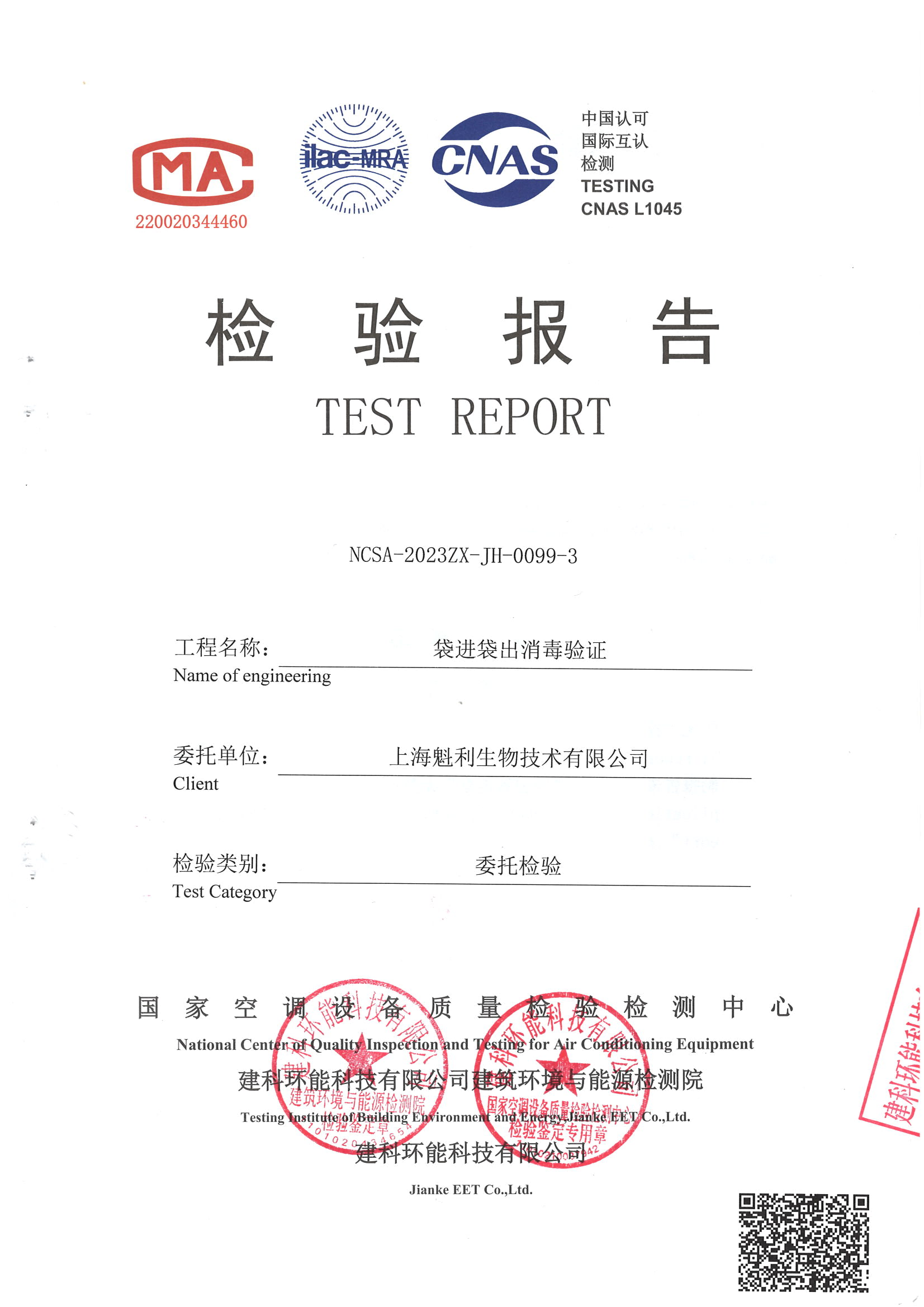
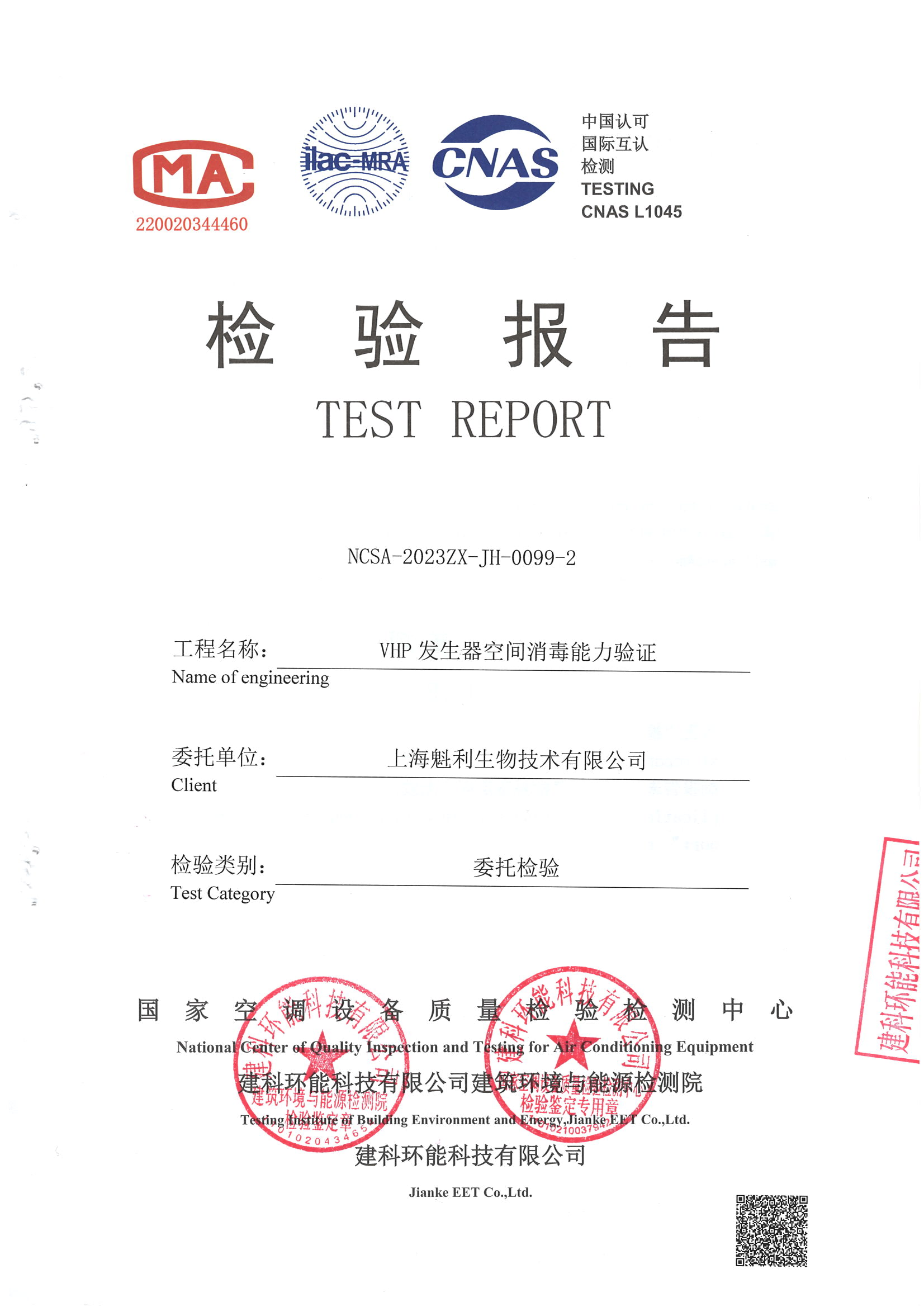
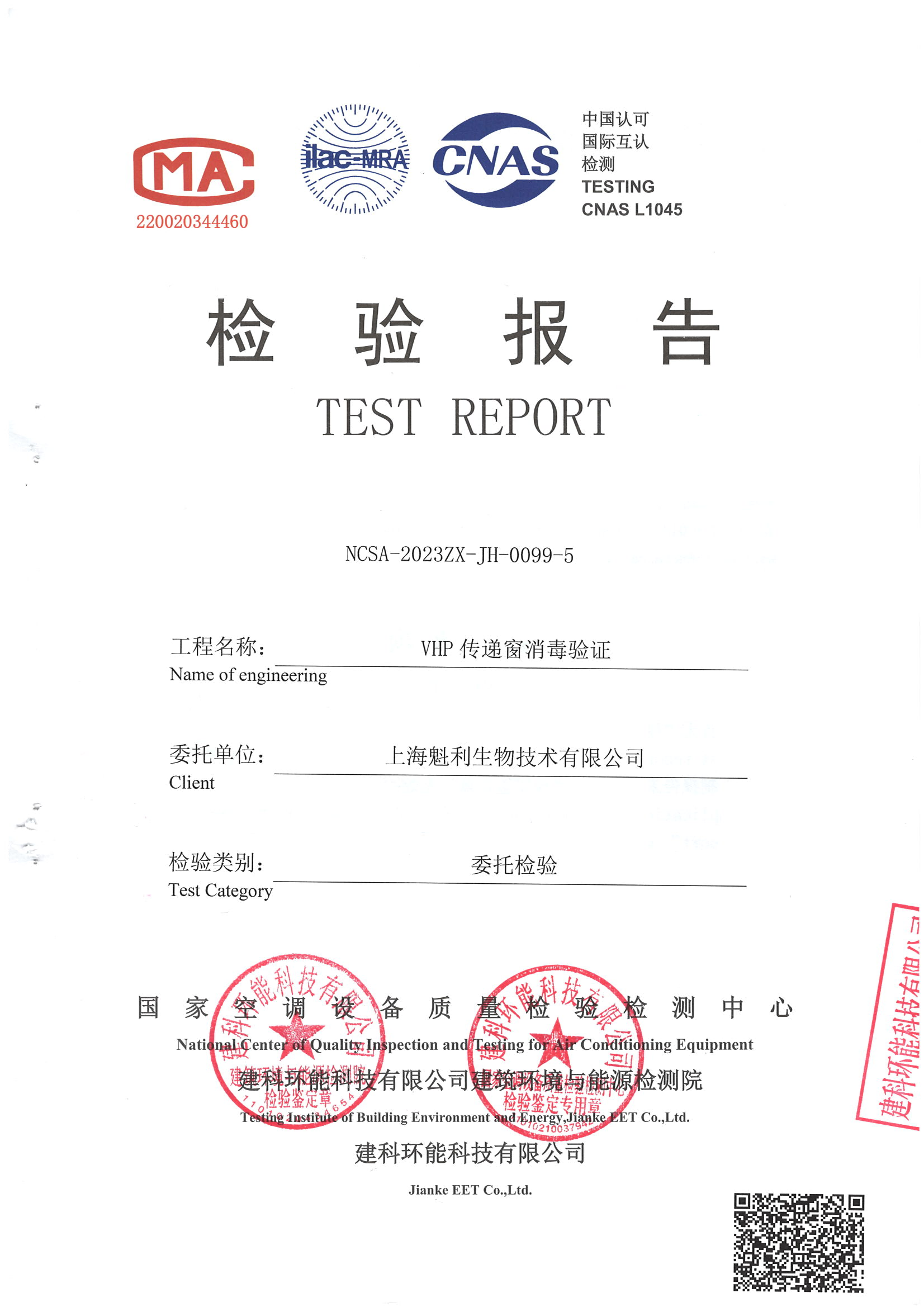
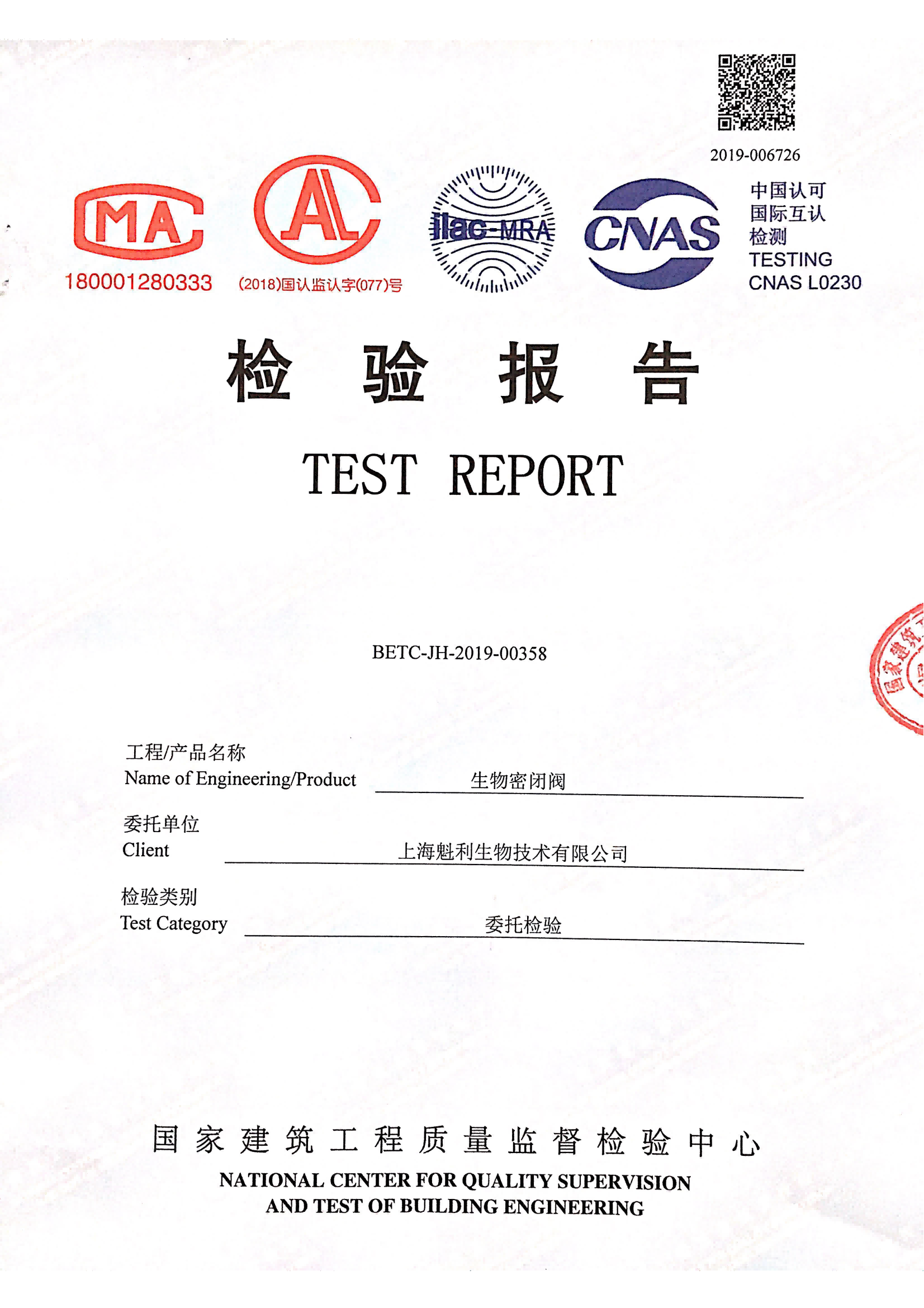
The OEB5 classification threshold of OEL <1 µg/m³ defines the exposure limit that the isolator system must keep operators below in normal operation. SMEPAC testing — conducted according to the ISPE Good Practice Guide methodology — provides the structured, traceable framework for verifying that the design achieves that protection level in practice. A SMEPAC result of <10 ng/m³ represents a design-level performance figure that, where achieved, demonstrates a significant margin below the OEB5 OEL threshold. These are not the same number, and they should not be conflated: the OEL is the classification criterion; the SMEPAC result is the measured containment performance under a defined test protocol. Third-party testing under ISPE SMEPAC guidelines replaces subjective pressure-trend interpretation with data that can be reviewed, compared, and defended during audit.
Two review checks at this gate are frequently underweighted. First, the scope of SMEPAC testing must cover the actual intervention paths that will occur in operation — not just the baseline chamber boundary. If powder transfer, glove changes, or sampling were not included in the test scope, the result does not confirm containment for those tasks, regardless of the headline figure. Second, alarm record integrity is an audit-readiness requirement with a direct GMP data integrity implication: alarm records that can be edited after the fact cannot be used to demonstrate continuous containment monitoring in a way that satisfies EU GMP Annex 1 data integrity principles. Non-editable alarm records are a confirmation item at design approval, not an afterthought for the software validation phase.
| Verification Requirement | Why It Matters | What to Confirm |
|---|---|---|
| Containment performance target | Ensures exposure stays below OEB5 threshold | OEL <1 µg/m³, demonstrated by third-party SMEPAC testing |
| SMEPAC testing methodology | Provides quantitative, traceable data instead of subjective readings | Test results <10 ng/m³, aligned with ISPE guidelines |
| Alarm record integrity | Supports GMP data integrity for validation and audits | Alarm records are non-editable |
Teams specifying OEB4/OEB5 containment systems will find the interface and qualification considerations covered across Qualia Bio’s OEB4/OEB5 isolator range directly relevant to the design gate criteria described here.
The most actionable implication of this article is also the one most consistently deferred: the intervention path map should be complete before the isolator model is selected, not after. Once a chamber configuration is locked, recovering containment coverage for tasks that were not accounted for requires adding interfaces — each of which carries a validation scope, a cleaning route, and a qualification burden that was not in the original project cost or schedule. The design approval gate is the point at which that map must be closed, with every material movement and operator task assigned a tested containment control and traceable verification data.
Before procurement or FAT scheduling, confirm that the SMEPAC test scope includes the actual intervention tasks expected in operation, that pressure control specification is treated as an accuracy-critical parameter in the URS, that chamber geometry and cleaning routes have been reviewed together rather than separately, and that alarm record non-editability is specified in the software requirements — not deferred to computerized system validation. These are the items most likely to surface as qualification deficiencies or audit findings when left unresolved at the design stage.
Frequently Asked Questions
Q: What happens if SMEPAC testing is scheduled after FAT rather than integrated into the design approval gate?
A: Scheduling SMEPAC post-FAT means containment gaps discovered during testing require hardware or interface changes that are significantly more expensive to recover at that stage. The test scope must reflect actual operation — if intervention tasks such as glove changes or sampling were not part of the original design review, a post-FAT SMEPAC result may achieve the <10 ng/m³ figure for the baseline chamber while leaving those tasks unverified. The approval gate only closes when the test scope matches the full intervention path map, not when the headline number is achieved.
Q: Is a single RTP port sufficient for a campaign involving both material introduction and product discharge, or do both directions require separate interfaces?
A: A single RTP does not cover both directions — it resolves one side of the transfer chain. RTP ports are designed for docked, closed introduction of material into the chamber; product discharge to an IBC requires a separate closed interface such as a twin valve. Treating one interface as covering both movements leaves the discharge path outside the tested containment boundary, which is a qualification gap regardless of the RTP’s individual performance. Each direction of material movement should be mapped to its own verified interface before the configuration is locked.
Q: At what point does adding more interfaces to an OEB5 isolator create more qualification risk than it resolves in containment coverage?
A: Each additional interface adds a discrete cleaning route, a validation scope item, and a boundary point requiring its own integrity verification — so the crossover point depends on whether the interface addresses a task that is already in the operation map or one that is being added opportunistically. Interfaces that resolve a defined material movement or intervention path are justified by the containment control they provide. Interfaces added without a corresponding mapped task inflate qualification scope without improving boundary coverage. The practical check is whether each interface traces back to a specific, anticipated operator task in the URS; if it does not, its inclusion should be re-evaluated before design lock.
Q: How should a facility weigh recurring single-use consumable costs against the cleaning validation savings they offer over a multi-year campaign lifecycle?
A: The break-even depends on campaign frequency and product changeover requirements rather than a fixed cost comparison. Single-use components reduce cleaning validation scope and can shorten inter-campaign turnaround, but introduce recurring consumable spend and a supply chain dependency that must remain uninterrupted throughout the system’s operational life. For facilities running high-frequency changeovers with tight schedule margins, the validation resource savings and reduced downtime typically outweigh consumable cost. For facilities with longer campaigns and stable product runs, the recurring cost of single-use components may exceed what a validated clean-in-place route would require over the same period. This trade-off should be modelled against projected run frequency before the cleaning strategy is fixed in the URS.
Q: If an ergonomic adjustment to glove port height is made after initial design approval, does the entire containment qualification need to be repeated?
A: Not necessarily in full, but the affected boundary sections must be reassessed for containment impact before the change is incorporated into qualification documentation. A port height change modifies the operator’s reach envelope and may alter glove sleeve configuration — both of which affect the tested intervention posture. If the modification falls outside the conditions covered by the original SMEPAC test scope, the tasks performed through that port should be retested under the revised configuration. Incorporating an unevaluated ergonomic change into a qualified system without a documented impact assessment creates a qualification-to-practice divergence that is difficult to defend during audit.
Related Contents:
- What Containment Level Does an OEB5 Isolator Provide?
- OEB4/OEB5 Isolator Cleaning: Effective Protocols
- OEB4/OEB5 Isolator Glove Integrity: Testing Methods
- Ensuring Compliance: OEB4 and OEB5 Isolator Standards
- GMP Compliance Guide for OEB4/OEB5 Isolator Usage
- 5 Essential Maintenance Tips for OEB5 Isolators
- Safeguarding Operators: The Power of OEB5 Isolator Technology
- Advancements in OEB4 and OEB5 Isolator Technology
- OEB4/OEB5 Glove Box Isolators: Handling Potent Compounds


