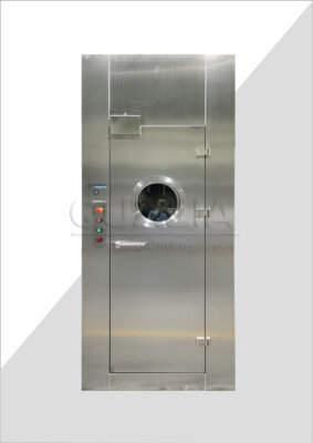
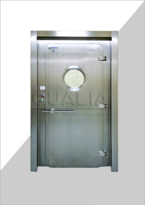
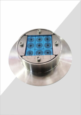
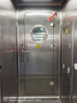
A cRABS layout looks finished once the enclosure geometry, glove port positions, and material transfer points are drawn to scale. But a layout freeze also fixes, often without anyone stating it directly, what cleaning staff can reach, what a technician can service without opening the barrier, and what happens to the enclosure’s controlled state when someone has to open it anyway. Confirming these access paths before freeze is cheaper than discovering their absence after the enclosure is built.
Map Cleaning and Disinfection Tasks to Every Accessible Surface
A cRABS layout implies a cleaning and disinfection plan whether or not that plan has been written down. Every interior surface, glove sleeve, transfer hatch, and mounted fixture accumulates residues relevant to the process running inside, and each of those surfaces needs a defined path by which someone or something reaches it, applies a disinfection method, and confirms the result. The layout question is not whether cleaning will happen but whether the geometry that gets frozen still allows it to happen on every surface that needs it.
This is where enclosure geometry and cleaning access start to conflict in ways that are easy to miss on a drawing. A support bracket, an instrument housing, a corner where two panels meet, or a component tucked behind a glove port can all become shadowed zones that a wipe or spray path cannot reach without a tool or a repositioned glove. Where a component sits flush against a wall with no clearance for an application tool, the drawing may look compact and efficient while quietly removing the access a cleaning procedure will need. The layout decision this creates is straightforward once identified: either the component is relocated to leave a viable path, or the project accepts a documented method for that specific geometry, but neither decision should happen implicitly through geometry that nobody checked against the cleaning task.
EU GMP Annex 1 addresses this directly for RABS by requiring that decontamination methods be defined and controlled and by expecting the enclosure to present cleanable surfaces. That expectation does not prescribe which agents, cycles, or acceptance values apply to a given project, and it should not be read as if it did. What it does establish is the underlying logic a layout review should apply: a surface only counts as part of the aseptic zone’s contamination control strategy if it can actually be reached, inspected, and confirmed clean, not merely if it is present inside the enclosure boundary.
Inspection points deserve the same scrutiny as cleaning paths. If disinfection coverage cannot be visually confirmed at some interior locations because the sightline is blocked by other equipment or by the enclosure’s own internal arrangement, that gap needs to be resolved before freeze, either by repositioning the obstruction or by defining an alternative confirmation method for that specific point. A layout that satisfies material flow and operator ergonomics but leaves cleaning verification unresolved has only solved part of the problem it was meant to solve.
Map Maintenance Tasks to Components and Access Routes
Cleaning access and maintenance access are related but not identical questions, and treating them as one collapses distinctions that matter to the layout. A surface can be reachable for a wipe or spray while remaining unreachable for a technician who needs to remove a component, replace an instrument, or reach a fastener with a specific tool. Maintenance access depends on clearance for hands, tools, and sometimes lifting equipment, not merely a line of sight or an application path.
Annex 1 states that equipment should be designed, where practicable, so that maintenance and repair can occur from outside the cleanroom, and that maintenance conducted inside the room may call for additional controls. This distinction should shape how the layout treats each component. A component whose service can realistically happen from outside the barrier, through a sealed interface or an accessible service zone, carries a different layout requirement than one whose repair can only happen by opening the enclosure itself. Where the first condition holds, the layout needs a confirmed external access route and enough clearance around that interface to actually perform the task. Where the second condition holds, the layout needs to account for what opening the barrier does to the controlled state, which is a different and larger question than access alone.
The practical test for each planned maintenance task is whether someone has actually traced the full route: the door or panel that opens, the tool required, whether the component can be lifted or slid out along that path without interference from neighboring equipment, and whether the surrounding cleanroom is affected by that action. A route that looks open on a two-dimensional drawing can be blocked in practice by a neighboring service line, an insufficient swing radius for a door, or a fastener oriented in a direction no tool can reach once adjacent equipment is installed. This is the condition under which a layout that appeared complete on paper turns out to need rework once a mock-up or a field walk-through is performed.
| Lifecycle task | Access evidence to confirm | Layout decision affected |
|---|---|---|
| Interior cleaning and disinfection | Surface map, tool path, viewing, and obstruction review | Door, panel, glove, and internal arrangement |
| Exterior cleaning | External surfaces, joints, supports, and nearby equipment | Clearance and cleanability around the enclosure |
| Routine inspection and glove work | Inspection points, glove access, and visibility | Port and observation arrangement |
| Instrument or component service | Component location, removal path, tools, and utility isolation information | Panel, door, and service-zone arrangement |
| Repair and reassembly | Opening needs, part movement, reassembly sequence, and room impact | Whether service can occur within the planned access concept |
| Recovery and release | Site-defined cleaning, monitoring, records, checks, and approval roles | What evidence is needed after work before authorized reuse |
Instrument and filter access, where applicable to the configuration, follows the same logic: calibration and adjustment tasks that are frequent enough to matter for operations should have a route that does not require full barrier opening, while tasks that are rare enough to accept a more disruptive access method can be planned around a documented, less frequent intervention path. Confirming which category each task falls into is a project-specific decision that the layout should reflect explicitly rather than assume.
Review Opening, Reassembly, and Return-to-Use Consequences
Every maintenance task that requires opening the barrier or otherwise disturbing the controlled state raises a second question beyond physical access: what has to happen before the enclosure is authorized for use again. This is where a layout review can quietly go wrong by treating access and recovery as the same problem. Confirming that a technician can physically reach a component says nothing about what cleaning, disinfection, monitoring, or approval steps follow once that access has been used.
Annex 1 frames this as a matter of restoring the controlled state through defined, site-specific steps rather than a single universal action. Opening a door or panel may trigger a need for re-cleaning of exposed surfaces, a disinfection cycle, environmental monitoring before resumption, and a set of project-defined checks that confirm the enclosure has returned to its required condition. Some of these steps carry documentation and approval requirements that involve quality or validation functions beyond the maintenance team performing the physical work. None of this should be assumed to happen automatically as a byproduct of closing the door.
The condition that changes this picture is the nature and frequency of the intervention. Where a task is expected to occur only rarely and under planned, scheduled conditions, the project may reasonably build a more elaborate recovery sequence into its procedures, since the operational cost of that sequence is incurred infrequently. Where a task is expected to recur as part of routine operation, the recovery burden compounds every time it occurs, and a layout that requires full barrier opening for a routine task creates a standing operational cost that a different component placement or a different access interface might have avoided. This is the reasoning that should inform which maintenance tasks get engineered toward external or sealed access and which are accepted as barrier-opening events with a defined recovery path.
The responsibility question matters here as much as the technical one. A layout freeze should not proceed on an implicit assumption about who performs the reassembly checks, who signs off on returning the enclosure to use, or which records are generated at each step. Where these roles and records are undefined, the access route itself may be physically sound while the operational sequence built around it remains unresolved, and that gap tends to surface only once the enclosure is in service and a real intervention is required.
Freeze the Layout Only When Access Evidence Is Closed
A layout freeze is a claim that every task the enclosure needs to support over its operating life has a confirmed, workable access path. That claim needs evidence behind it, not just a completed drawing. Acceptable evidence takes several forms: a dimensioned drawing showing genuine clearance for the tool and hand movement a task requires, a field observation or mock-up that physically confirms a route works as drawn, service information from the component manufacturer describing its removal or access requirements, or, where none of these yet exist, an explicit project decision that names the open question and assigns responsibility for closing it before construction proceeds.
What does not qualify as evidence is an assumption. A clearance that “should be enough,” a component that “should be removable that way,” or a maintenance responsibility that “someone will sort out” are exactly the gaps that surface later as field rework, procedural improvisation, or disputes over who owns an unplanned task. A layout can legitimately remain open on a specific point while the rest proceeds, but that openness needs to be visible and tracked rather than silently absorbed into a frozen drawing.
This is also where the project’s own input quality determines how much a supplier conversation can resolve. The component locations, access assumptions, and task lists a project team brings into a configuration or quotation review with a supplier like QUALIA shape how precisely that review can confirm whether a proposed cRABS configuration actually supports the access the project needs. A review built on a well-documented task list can identify mismatches early; a review built on an undocumented layout can only confirm what was assumed, not what was verified.
The distinction worth holding onto through this process is between physical accessibility and operational readiness. A route can be physically open while the procedure around its use remains undefined, and a procedure can be well-defined while the physical route it depends on turns out to be obstructed once real components are installed. Where a project treats these as one question, gaps in either dimension get missed. Where a project checks them separately, against drawings, field verification, and explicit decisions, the layout that gets frozen is one whose cleaning, maintenance, and recovery tasks have actually been tested against the geometry, not merely assumed to fit within it.
Frequently Asked Questions
Q: Can we confirm cleanability simply by showing that a door opens?
A: Door access is useful, but the review must also show how cleaning tools reach the relevant surfaces and how those surfaces can be inspected. Map residues, application paths, viewing needs, and shadowed or obstructed areas against the proposed internal arrangement.
Q: Why should component removal be checked before layout freeze?
A: A component may be reachable for inspection yet lack a workable removal or repair path. Show the component location, tools, handling needs, panel or door openings, and surrounding room impact so the service arrangement can be evaluated before it becomes a fixed layout constraint.
Q: Does closing the barrier after maintenance establish readiness for production?
A: Return to use also depends on the site’s defined recovery and release requirements. Identify any reassembly, cleaning, disinfection, monitoring, checks, records, and approval dependencies associated with the work rather than treating physical closure as the whole recovery decision.
Q: What evidence is useful when an access task cannot be confirmed on a drawing?
A: Use field observation, a mock-up, or relevant service information to address the specific task. If clearance, removal, or responsibility remains unverified, retain it as an explicit open decision so layout approval does not silently rely on an assumption.