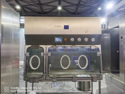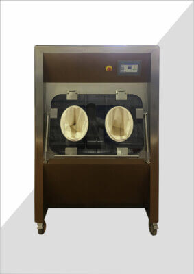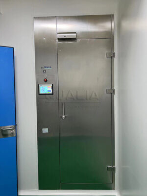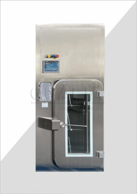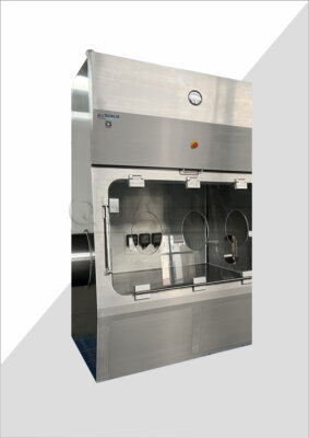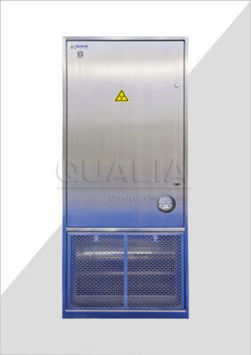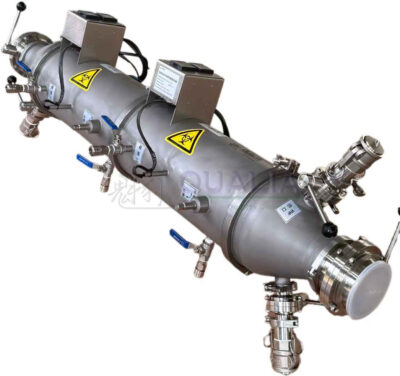

A material transfer URS determines whether a pass box, dunk tank, or VHP transfer system can be evaluated against a real operating case or only against a generic datasheet. The document governs how a supplier prices, configures, and qualifies equipment that moves loads across a biosafety or containment boundary, and gaps in it surface later as FAT deviations, SAT delays, or disputed acceptance criteria. Getting the requirement set right before issuing an RFQ is what lets a technical buyer compare proposals on equal terms.
Translate the operating case into measurable user requirements
A URS exists to convert an operating case into statements a supplier can design against and a qualification team can verify against. This translation step is where most ambiguity enters a project, because an operating description (“we move samples from the lab into the corridor”) is not yet a requirement until it specifies the load, the boundary, the cycle, and the acceptance condition tied to each.
The translation task differs depending on which protection objective governs the transfer. Where the boundary protects personnel and the environment from a hazardous or biological agent, the requirement set is built around containment integrity, decontamination efficacy, and controlled access from the contained side. Where the boundary protects a product from contamination, the requirement set is built around maintaining a clean or sterile condition on the protected side and controlling what enters it. A single piece of transfer equipment, such as a pass box or a VHP pass box, may sit at either kind of boundary, and the same physical component will carry a different requirement logic depending on which side the project is protecting. Stating this governing objective at the top of the URS prevents downstream confusion when interlocks, alarms, or cycle logic are specified later, because a requirement that reads as reasonable for a containment boundary can be wrong for an aseptic boundary, and the reverse.
Measurability is the second translation task. A requirement that states an intent without a verifiable condition cannot be closed at FAT, SAT, IQ, or OQ, because there is no observable pass/fail basis. Under the EudraLex Volume 4 Annex 15 qualification framework, the URS remains a reference across the validation life cycle, and design qualification verifies that the design meets the URS requirements; a requirement that cannot be checked at that stage has no path to closure. This means each operating-case statement needs an associated condition: what is loaded, from where, to where, under what cycle state, with what release logic, and what evidence will confirm it. Where the project team cannot yet state a measurable condition for a requirement, that gap belongs on the open-items list the RFQ carries forward, not folded into a vague specification that a supplier cannot price or verify.
The practical effect of this section’s work is that every later section of the URS inherits its discipline from here: if the operating case and governing objective are not fixed first, the load schedule, boundary definition, and cycle logic that follow will each carry the same ambiguity forward.
Describe every load and the transfer direction it must follow
| Load schedule input | What the URS should state for each load | Decision supported |
|---|---|---|
| Maximum dimensions | The maximum dimensions of the load | Whether the proposed transfer path accommodates the largest load |
| Mass | The maximum mass of the load | Whether the proposed configuration matches the load case |
| Packaging | The packaging presented for transfer | Which packaging condition the proposed transfer case covers |
| Surface condition | The surface condition at transfer | Which surface condition the process and evidence must address |
| Material compatibility | The materials that require compatibility confirmation | Which materials are covered and which remain project-specific |
| Permitted orientations | The orientations allowed during transfer | How the load may be positioned within the defined operating case |
| Transfer direction | The required direction across the boundary | Which direction or directions the transfer arrangement must support |
A load schedule is only useful to a supplier if it describes the actual material the equipment must move, not a generic class of material that happens to resemble it. A requirement stated as “standard laboratory consumables” invites a supplier to design to its own assumption of what that means, and that assumption may not match the heaviest, largest, or least compatible item the project will actually transfer. The schedule should instead identify the maximum dimensions, maximum mass, the packaging condition presented at the boundary, the surface condition of that packaging, which materials require compatibility confirmation, and which orientations are permitted during transfer.
Each of these inputs changes a different part of the proposed configuration. Dimensions and permitted orientation determine whether the transfer path and door opening accommodate the largest anticipated load without forcing an orientation the packaging cannot tolerate. Mass affects shelving, support, and any mechanized transfer path. Packaging and surface condition matter because a decontamination cycle, where one is part of the operating case, interacts with the exposed surface; a packaging type or surface condition not included in the project’s load schedule is a packaging type or surface condition the cycle evidence does not cover, regardless of what the general equipment capability allows. Material compatibility works the same way: confirming compatibility for one material does not extend to a different material introduced later without a review.
Transfer direction is a distinct requirement from the load description itself. A boundary that must support loads moving only from an uncontained or unclassified side into the contained or protected side has a different interlock and validation logic than one that must also support the reverse direction, or both directions under different cycle states. Where a project anticipates that the direction requirement may expand later, for example a one-way transfer that may later need to support material leaving a contained area, stating that possibility in the URS lets the supplier assess whether the proposed configuration has a credible path to that capability, rather than requiring a replacement system.
Leaving any of these fields unspecified does not remove the requirement; it transfers the decision to the supplier’s default assumption, which the project then discovers only at FAT or later.
Fix the boundary, room interfaces, utilities, and service access
| Interface decision | Project-specific URS entry | What it establishes |
|---|---|---|
| Protected boundary | Identify which side is clean or contained | The boundary the transfer arrangement must protect |
| Door access | State who may open each door | The permitted access from each side of the boundary |
| Room interfaces | Define the interface condition on each side | The operating case at both ends of the transfer |
| Utilities | List the utilities required for the selected configuration | The utility scope suppliers must include in the same priced case |
| Service access | State the required service access condition | The access constraint that must be accommodated at the installation interface |
The boundary definition is the point where the URS stops describing the equipment in isolation and starts describing how it sits inside a real facility. The first fact every reviewer needs is which side of the boundary is clean or which side is contained, because every subsequent interlock, door-access rule, and failure-state decision depends on that designation. A requirement written without stating which side is protected is incomplete even if every dimension and mass figure is correct, because the supplier cannot determine which side’s integrity the control logic must prioritize when a failure occurs.
Door access follows directly from the boundary designation. Stating who may open each door, under which conditions, and from which side is not a redundant restatement of the interlock logic; it is the operational policy that the interlock logic will later enforce in hardware and software. A project that defines this access policy loosely risks a supplier building interlocks that are technically functional but do not match how the site intends to operate the equipment day to day.
Room interfaces describe the condition the equipment must match on each side: the classification, pressure regime, or containment status of the space the transfer equipment connects to. This differs from the boundary designation because a room interface condition can change independently of which side is “protected” — a room may be reclassified, or a pressure cascade may be adjusted, without changing which side of the transfer equipment is clean or contained. The URS should state the interface condition the equipment must be compatible with, so a later facility change can be checked against that stated condition rather than assumed.
Utilities and service access round out the boundary definition because they determine what the installed configuration actually requires from the building and what access the site must preserve afterward. Listing the utilities required for the selected configuration lets the project confirm the facility can supply them at the intended location; omitting this risks a configuration that performs as specified but cannot be installed without facility rework. Service access works the other way: it is a constraint the facility places on the equipment, stating what clearance or access condition must be preserved so that maintenance can occur without compromising the boundary. This is one point where the information a project supplies — the governing boundary, interface, and utility conditions — becomes the basis QUALIA uses to configure and quote a transfer solution against the stated case, rather than against a generic product description.
Specify cycle states, interlocks, alarms, bypasses, and recovery
| Control point | What the URS should define | Decision boundary |
|---|---|---|
| Process phases | The required cycle phases | The states included in the specified operating sequence |
| Monitoring points | The points monitored during the cycle | Where the specified cycle condition is checked |
| Load patterns | The load patterns the cycle requirement covers | Which operating cases the cycle evidence must match |
| Door interlocks | Who may open each door and in which cycle state | When access is permitted on each side |
| Alarms and bypasses | The alarm conditions and any permitted bypasses | Which exceptions are allowed and which remain outside normal operation |
| Failure recovery | The safe state after power, pressure, sensor, or cycle failure | The required outcome when the normal sequence cannot continue |
| Release logic | The logic used to release the load | The condition that separates an incomplete cycle from an eligible release |
| Requalification triggers | The events that require requalification | When existing qualification evidence is no longer sufficient for the defined case |
Cycle and interlock requirements are where the URS defines how the equipment behaves during normal operation and how it behaves when something goes wrong, and both halves need to be specified with the same rigor. The normal-operation half starts with naming the process phases the cycle must include and the points at which the cycle is monitored. This matters because a cycle requirement stated as an outcome (“the load must be decontaminated”) without naming the phases and monitoring points gives the supplier no basis for proposing a specific sequence, and gives the validation team no checkpoints to verify against later. EU GMP Annex 1 addresses this kind of structure in the sterile-manufacturing context, describing transfer controls and validated bio-decontamination cycles operating within defined cycle parameters; the general principle — that a cycle is defined by its phases, monitored points, and validated parameters, not by its intended result alone — applies broadly, though the specific cycle recipe is never universal and remains a project-specific determination.
Load pattern matters because a cycle validated for one arrangement of loads does not automatically extend to a different arrangement. Where the project’s load schedule includes items of varying size, density, or packaging, the URS should state which load patterns the cycle requirement must cover, so the qualification evidence generated later actually matches what operators will load in practice rather than a single idealized configuration.
Door interlocks tie back to the boundary definition: this section specifies who may open each door and in which cycle state, converting the general access policy into a condition checked against the cycle’s actual state machine. Alarm and bypass requirements then define the exception space — which conditions trigger an alarm, and which of those allow an operator-initiated bypass versus which must halt the process entirely. A bypass that is undocumented in the URS but exists in the delivered control system becomes a qualification finding rather than a planned feature.
Failure recovery requirements state the safe state the equipment must reach after a power, pressure, sensor, or cycle failure, and this differs by boundary type: a containment boundary’s safe state generally prioritizes keeping the contained side sealed, while an aseptic boundary’s safe state prioritizes keeping the protected side from being exposed to an uncontrolled environment. The same failure event can require a different equipment response depending on which objective governs the boundary, which is why this requirement cannot be copied from a different project without checking the governing objective first.
Release logic and requalification triggers close the loop: release logic states the condition that separates an incomplete cycle from one eligible for load release, and requalification triggers state which events — a component change, a deviation, a time interval — mean existing qualification evidence no longer applies to the defined case. ISO 14644-7 notes that separative-device user requirements are a matter agreed between customer and supplier and that the standard does not specify the process installed inside the device, which is why these cycle and interlock parameters have to be stated explicitly in the project’s own URS rather than assumed from the device category.
Map each requirement to supplier documents and qualification evidence
A requirement without an evidence destination is a statement of intent, not a verifiable specification. Each line in the URS — load schedule entry, boundary condition, cycle phase, interlock rule, alarm condition, release criterion — needs an associated point in the project’s documentation chain where a supplier or user demonstrates that the requirement has been met. That destination is typically one of a supplier’s own test documents, a factory acceptance test, a site acceptance test, an installation qualification, an operational qualification, or site process evidence generated once the equipment is in routine use.
The choice of destination is not arbitrary and depends on what the requirement actually verifies. A dimensional or mass requirement is often confirmable through supplier documentation and a factory test, because the physical feature does not depend on the installed environment. A requirement tied to the room interface or to a utility connection generally cannot be closed until the equipment is installed on site, because the behavior being verified only exists once the equipment interacts with the actual facility. A cycle performance requirement may need evidence from multiple stages: a factory test confirming the control sequence executes as designed, a site test confirming it executes correctly once installed, and a qualification stage confirming the cycle performs against defined parameters under site conditions. Under the Annex 15 framework, design qualification is the stage that checks the design against the URS, which makes this mapping work a precondition for that check rather than a parallel activity — a requirement that was never assigned an evidence destination cannot be meaningfully verified at design qualification, because there is nothing to point to.
Where a requirement’s evidence destination is left unstated, the decision of where and how to verify it defaults to whichever party controls the test protocol at that stage, which may not match the project’s actual expectation. A project team that leaves this mapping incomplete going into an RFQ is effectively asking suppliers to each decide independently where their scope of proof begins and ends, which makes supplier responses harder to compare on equal terms. Making this mapping explicit, even provisionally, gives both the supplier and the user a shared understanding of where conformity will be demonstrated before contracts are signed.
Freeze acceptance responsibilities before issuing the RFQ
Before an RFQ goes out, the project needs to decide who performs each piece of verification work and who accepts the result, separately from deciding what the requirement is. A requirement can be fully and clearly specified and still generate a dispute at delivery if the project never fixed whether the supplier’s factory test is sufficient for a given requirement or whether the user’s own site test must independently confirm it. This is a distinct decision from the evidence-mapping work, because mapping identifies where a requirement will be checked, while acceptance responsibility decides who performs that check and who has authority to sign it off.
This matters most at the boundaries between acceptance stages. A factory acceptance test performed at the supplier’s premises demonstrates that the equipment functions as built, under conditions the supplier controls. A site acceptance test demonstrates the same functions once installed, under the project’s actual utilities and room interfaces, which is why requirements tied to room interface or utility conditions often cannot be closed at the factory stage regardless of how thoroughly the supplier tests beforehand. If the project has not stated in advance which requirements it expects to see closed at each stage, a supplier proposal may allocate verification differently than the project assumes, and that mismatch only becomes visible once the equipment arrives and someone asks why a requirement wasn’t tested where they expected.
Freezing these responsibilities before the RFQ also protects the comparability of supplier responses. Where one supplier proposes to close a given requirement at FAT and another proposes to defer it to SAT or OQ, their quotations are not directly comparable unless the project has already stated where it expects that requirement closed. Making this expectation explicit in the URS, even as a stated preference the project is open to discussing, gives every bidder the same baseline to price against.
The requirements this section governs are the ones most likely to depend on project-specific priorities: whether the user’s own qualification team must witness certain tests, whether bio-indicator or chemical-indicator support for a cycle is the supplier’s responsibility or the user’s, and which party holds responsibility for requalification once equipment is in service. These allocations are not implicit in the technical requirement itself and need to be stated as their own line items before a request for quotation goes out, so that the responses QUALIA or any other supplier returns can be evaluated against a shared, pre-agreed division of acceptance work rather than reconciled after the fact.
Frequently Asked Questions
Q: What must be fixed before suppliers can price the same material transfer case?
A: Define the actual loads, transfer direction, protected boundary, room interfaces, required utilities, service access, and permitted door access. Also state the cycle, interlock, alarm, recovery, and release conditions that belong to the priced case so differences between quotations reflect the proposed solution rather than different assumptions.
Q: Can one maximum load description cover every material transfer?
A: Only if every intended load shares the same relevant conditions. Separate load patterns when dimensions, mass, packaging, surface condition, material compatibility, permitted orientation, or transfer direction differ, and identify which patterns the proposed configuration and its evidence must cover.
Q: How specific should the cycle requirements be when the final operating recipe is not yet confirmed?
A: Specify the required process phases, monitoring points, covered load patterns, release logic, and requalification triggers without inventing fixed cycle values. Project-specific parameters and acceptance criteria can then be confirmed against the selected configuration and qualification approach.
Q: What should the URS require after a power, pressure, sensor, or cycle failure?
A: State the safe condition for the load and both doors, who may act from each side, and whether any bypass or recovery step is permitted. Define the evidence needed before the sequence can resume or the load can be released, rather than leaving recovery behavior to an unstated supplier assumption.
Q: How can acceptance gaps be found before the RFQ is issued?
A: Link each requirement to the document or test stage where conformity will be demonstrated, such as supplier documentation, FAT, SAT, IQ, OQ, or site process evidence. Assign responsibility for providing and approving that evidence, while keeping the exact stage and acceptance criteria specific to the project.