A biosafety HVAC drawing can show three dampers that all close, and all three can look identical on a schematic. The decision a project team faces is not whether a damper can reach the closed position, but which duty it was selected, configured, and evidenced to perform. Confusing isolation duty with backdraft response or routine control modulation creates gaps that only surface during fail-state conditions or during qualification review, when the evidence requested does not match the duty assumed.
Three damper functions that project teams often combine
| Damper function | Primary duty | Decision boundary |
|---|---|---|
| Isolation | Deliberate closure at a defined containment boundary | Specify containment duty and its supporting evidence; a blade that can close does not by itself establish containment duty |
| Backdraft | Response to reverse-flow conditions | Use for reverse-flow protection rather than treating it as deliberate containment isolation |
| Control | Modulation of normal HVAC airflow | Use for routine airflow control rather than treating a closed position as proof of containment isolation |
An isolation damper provides deliberate boundary closure, a backdraft damper responds to reverse flow, and a control damper modulates normal airflow. These are three different design intents, and a project drawing that shows “a damper” without naming which duty it serves leaves that distinction unresolved until someone has to defend it.
The confusion arises because all three devices share a mechanical vocabulary: a blade, an actuator or spring return, and a closed position. Where a reviewer sees a damper that can close, the instinct is to treat that closed position as containment capability. This instinct does not hold. A backdraft damper closes because reverse flow pushes a gravity-actuated or spring-loaded blade shut; it was not sized, sealed, or tested against a defined boundary. A control damper closes or modulates based on a control signal tied to airflow balancing, not to a containment event. Neither device carries the leakage evidence, actuator behavior, or position feedback that an isolation duty requires, even though the physical motion looks the same from outside the ductwork.
The practical consequence is that the project team must decide, for every damper location in the HVAC design, which of the three duties that location actually needs before selecting a device. Where a boundary must be sealed on demand during an alarm, maintenance, or decontamination event, the location needs isolation duty, and the specification must say so explicitly rather than relying on a general description of a “closing damper.” Where the concern is reverse flow during fan shutdown or system imbalance, the location needs backdraft protection, and the acceptance expectation is different: a backdraft damper is evaluated on how it behaves under reverse-flow conditions, not on sealed-boundary leakage performance. Where the location is part of ordinary airflow balancing, a control damper is the appropriate device, and asking it to double as a containment boundary device introduces a function it was not selected to perform.
This distinction changes how the reader evaluates a mechanical schedule or a supplier’s equipment list: each line item should name a duty, not just a device type, before leakage class, actuator type, or test method is discussed.
Isolation duty at a defined containment boundary
Isolation duty exists at a specific point in the system: wherever the design defines a containment boundary that must be deliberately and verifiably closed, independent of airflow direction or control logic. The defining feature is deliberateness. An isolation damper is commanded to close, or is held closed, because a condition requires that boundary to be sealed, and the design intends for that closure to be proven, not inferred from a blade position.
The condition that changes the judgment here is how the boundary is defined in the HVAC sequence. If the containment boundary is only meaningful during specific events, such as a decontamination cycle or a maintenance isolation, the isolation damper’s duty is tied to those events, and the actuator logic, fail-state position, and interlock behavior must be defined for each one. If the boundary is meant to hold under all operating conditions, including normal operation, the duty is continuous, and the leakage evidence expected is correspondingly broader. A project team reviewing a mechanical schedule needs to know which of these conditions applies at each isolation point, because the same physical damper selected for an intermittent duty may not satisfy a continuous boundary requirement, and the reverse substitution is equally invalid.
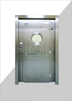
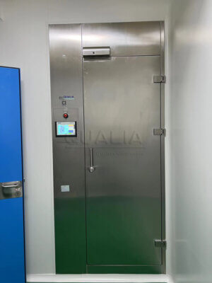
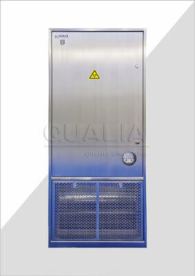
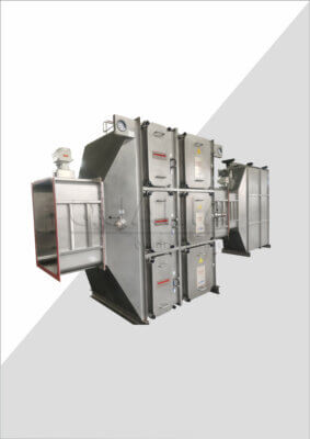
Leakage evidence is what separates an isolation damper from a device that merely closes. A closed blade position says nothing about how much air or contaminant passes the seal under the differential pressure the boundary is expected to hold. The project specification needs to state what leakage evidence is required for that specific boundary, and under what differential condition it is measured, before a device is accepted as fulfilling isolation duty. This is the point where BMBL’s description of BSL-4 fan-interlock and alarm context becomes relevant to the reader’s own facility: a directional-airflow or negative-pressure design that depends on fan interlocks and alarms needs isolation points whose closure behavior is defined for those same interlock and alarm conditions, not assumed from general damper capability. Reviewing QUALIA’s bio-safety isolation damper documentation against this boundary-specific evidence is one way a project team confirms that a selected device matches the duty the design assigns to that location, rather than matching the duty to the device after the fact.
Backdraft protection under reverse-flow conditions
A backdraft damper’s duty is to respond to reverse flow, not to serve as a commanded containment boundary. The blade typically moves passively, driven by the airflow differential itself or by a simple spring return, rather than by an active control signal tied to a containment event. This passive response is the functional strength of a backdraft damper: it protects against an unintended reverse-flow condition, such as what can occur on fan loss, without depending on a control system remaining active.
The condition that matters here is what the design expects to happen when the reverse-flow condition ends. A backdraft damper that closes under reverse flow and reopens once normal flow resumes is doing exactly what it was selected to do; expecting that same device to remain sealed as a deliberate isolation boundary during a subsequent event misapplies its duty. Where a project team is tempted to rely on a backdraft damper for isolation duty because it already closes under certain conditions, the gap appears in the leakage evidence and in the actuator behavior during conditions a backdraft damper was never evaluated against, such as a decontamination cycle or a commanded isolation unrelated to reverse flow.
This is also where the HVAC sequence needs to state, for fan loss and power loss specifically, which devices are expected to respond and how. A backdraft damper’s response to fan loss is part of its basic function; an isolation damper’s behavior during fan loss depends on how its fail-state position was specified, and the two should not be assumed identical merely because both devices may end up closed when the fan stops.
Control modulation during normal HVAC operation
A control damper’s duty is airflow modulation during normal operation, adjusting position in response to a control signal to maintain balance, pressure relationships, or flow setpoints across the system. Its closed position, where the design allows one, is a control state within normal operating range, not a response to an abnormal or hazardous condition.
The condition that distinguishes a control damper’s closed position from an isolation damper’s closed position is what triggers it. A control damper closes or nearly closes because the control loop calculates that airflow balance requires it, under conditions the system is designed to operate within. This is a routine, reversible, and frequently cycling behavior in some applications, which is itself a reason not to rely on a control damper for boundary duty: a device designed for continuous modulation is not evaluated against the leakage and fail-state requirements that an isolation boundary needs, and treating its closed position as a containment event conflates normal operation with an exceptional one.
Where a project’s HVAC sequence assigns a control damper a role during alarm, decontamination, or maintenance conditions beyond its normal modulation duty, that assignment needs its own actuator behavior and position feedback specification, distinct from its control-loop behavior during normal operation. Leaving that gap unspecified means the device’s behavior during an abnormal condition is undefined, even though its behavior during normal operation is well understood.
URS language that separates fail-state, leakage, and testing
| URS item | What the project should state | Decision value |
|---|---|---|
| Functional duty | Whether the device provides deliberate boundary closure, reverse-flow response, or normal airflow modulation | Prevents one damper function from being assigned another function’s duty |
| Leakage evidence | The leakage evidence required for the assigned duty | Prevents a closed blade position from being treated as sufficient containment evidence |
| Actuator behavior and HVAC sequence | What each device does during fan loss, power loss, alarm, decontamination, and maintenance | Makes operating and fail-state responses explicit for the project |
| Position feedback | The position feedback required for the assigned function | Separates feedback requirements from functional duty and leakage evidence |
| Acceptance testing | Project-specific tests and predefined acceptance criteria, with deviations documented | Defines how the specified duty and behavior will be accepted for the project |
The distinctions among isolation, backdraft, and control duty only hold through design and installation if the URS states them separately rather than letting one general damper description cover all three. EudraLex Volume 4 Annex 15 describes the URS as a life-cycle reference document, with predefined acceptance criteria and documented deviations carried through qualification; that life-cycle role is what makes early precision in the URS consequential rather than a formality that occurs once and is forgotten.
Functional duty should be stated first, naming whether a given device provides deliberate boundary closure, reverse-flow response, or normal airflow modulation, because every other line in the URS depends on knowing which duty applies. Leakage evidence should then be defined for the assigned duty specifically: an isolation point needs leakage evidence tied to its boundary condition, while a backdraft or control damper’s acceptance is based on its functional response rather than a sealed-boundary leakage figure. Actuator behavior and the HVAC sequence need to state what each device does during fan loss, power loss, alarm, decontamination, and maintenance, because a device’s behavior during normal operation says nothing about its behavior during these conditions unless the URS requires it explicitly. Position feedback should be specified according to what the assigned function needs, since an isolation duty may require confirmed position reporting that a control damper’s normal modulation does not.
Acceptance testing closes the loop: Annex 15 notes that a justified FAT may be supplemented by SAT, with protocols using predefined acceptance criteria and documented deviations. For a project team, this means the URS should state which tests apply to which duty before FAT or SAT planning begins, rather than discovering during testing that a device’s assigned duty was never matched to an acceptance method. Where a project’s HVAC design was developed alongside directional-airflow or negative-pressure logic, as described in related guidance on BSL-3 HVAC design covering negative pressure, directional airflow, HEPA exhaust, and alarm logic, the isolation points in that design carry their own fail-state and leakage requirements, and the URS submitted for supplier or project review should reflect that separation before a quotation or configuration review proceeds. Supplying that detail at the URS stage gives the project information QUALIA’s configuration review needs to confirm which duty a given damper location requires, rather than leaving that determination to be resolved after equipment has already been selected.
Frequently Asked Questions
Q: Can one damper be assigned more than one HVAC function?
A: Only when each assigned function is stated separately and supported by the corresponding leakage evidence, actuator behavior, position feedback, and acceptance testing. A blade that can move to a closed position does not by itself establish containment isolation.
Q: What should be defined before comparing damper proposals?
A: Map each device to a specific boundary and duty, then document its required response during normal operation, fan loss, power loss, alarm, decontamination, and maintenance. This gives bidders a consistent basis for showing how their proposed device and controls meet the project sequence.
Q: Should fan loss and power loss be treated as the same design condition?
A: No. Define the required device response and position feedback for each condition in the HVAC sequence, because the project must verify the intended behavior rather than infer it from a general fail-state description.
Q: How can a buyer compare evidence from different damper suppliers?
A: Compare the evidence against the assigned duty instead of comparing product labels alone. For each proposal, check the stated function, applicable leakage evidence, actuator response, position feedback, and the project-specific test and acceptance criteria.
Q: Does the biosafety level alone determine which damper function is required?
A: No. Use the facility’s airflow and containment strategy to define the required duty at each location; biosafety guidance provides context such as directional airflow, pressure, fan interlocks, and alarms, but the exact device function and acceptance criteria remain project-specific.