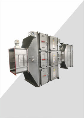
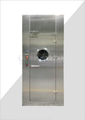
A duct that arrives on site as round or rectangular is already a decision that was made somewhere earlier in the project, and reversing it later costs more than confirming it early. Choosing between a round and a rectangular registre d'isolation de biosécurité is not a matter of preference; it is a question of which shape the connected ductwork, airflow target, and containment duty actually support. The two geometries behave differently enough in installation, pressure drop, sealing, and service access that the decision deserves its own review before a damper is specified into a drawing package.
Duct geometry and available installation envelope
The starting point for shape selection is what is already fixed: the connected ductwork and the space available to route it. Round dampers align naturally with circular ductwork, which is common where duct runs are long, pressure classes are higher, or the system was designed around round spiral duct for its structural and sealing properties. Rectangular bodies, by contrast, can fit a routing envelope that is shallow or wide rather than deep, which matters where ceiling voids, shaft dimensions, or structural beams constrain the available cross-section in one direction more than the other.
This means the choice is rarely free-standing. A damper selected before the duct geometry is confirmed risks a mismatch that forces a transition piece, a change in duct fabrication, or a rework of the surrounding support structure. Where the ductwork upstream and downstream of the damper is already round, introducing a rectangular damper means adding transitions on both sides, each of which is an additional joint, an additional point to seal, and an additional pressure-drop contributor. Where the available envelope is wide and shallow, forcing a round damper into that space can require a diameter that does not fit, or a reduction in duct size that changes the velocity and resistance the system was designed around.
The practical implication is that geometry should be read from the installed condition, not selected from a catalog page in isolation. A project team reviewing options should confirm the duct shape and size immediately upstream and downstream of the proposed damper location, the clear dimensions of the installation envelope in both directions, and whether any transition pieces would be required to connect the chosen damper shape to the existing or planned ductwork. Where the envelope allows either shape without a transition, the decision moves to the other factors covered through this comparison; where it does not, geometry itself narrows the choice before pressure drop, sealing, or actuator access are even considered.
Pressure-drop effects of face area and blade arrangement
Once geometry narrows the candidate shapes, the next judgment is whether each candidate actually delivers the airflow the system needs at an acceptable resistance. This is where nominal size becomes a misleading shortcut. A damper’s nominal width or diameter describes its outer dimension, not the open area through which air actually passes once the frame, blade stack, and seals are accounted for. Two dampers with the same nominal size in different shapes, or even in the same shape from different blade arrangements, can present different free areas and therefore different resistance at the same design airflow.
The mechanism behind this is straightforward: pressure drop across a damper is a function of the velocity through its free area, and free area is reduced by the frame depth, the blade thickness, the blade arrangement, and the sealing method, all of which vary with shape and configuration. A round body with a single-blade or multi-blade arrangement loses area differently at its perimeter than a rectangular body with parallel blades, because the geometry of how blades nest into a circular versus a rectangular frame is not the same. This is also where the relationship between shape and resistance connects to the broader question of Quelles sont les causes de la chute de pression dans les clapets de biosécurité ? generally, since face geometry is one contributor among several that determine how a given damper performs once installed.
The consequence for selection is that the buyer cannot compare round and rectangular options on nominal size alone. Each option needs to be sized against the same design airflow and the same acceptable system resistance, with free area and blade arrangement confirmed for the specific configuration under consideration, not assumed from the nominal dimension. Where the system has tight resistance margins, because fan capacity or room pressurization cascades were set against a narrow allowance, this sizing step carries more consequence: a shape or blade arrangement that trades away free area can push the system outside its design envelope even though the damper’s outer dimension matches what was specified. Where margins are wider, the shape-driven difference in free area may be absorbed without affecting downstream performance. Either way, the buyer should request the free area and resistance data for the actual configuration being quoted, not a generic value for the nominal size.
Sealing, flange, and fabrication implications by shape
Shape also changes how the damper connects to the duct and how its casing behaves under load, and both of these affect the containment duty the damper is meant to perform. Flange joints are fabricated differently for round and rectangular bodies: a round flange relies on a continuous circular seal, while a rectangular flange has corners, where sealing geometry is harder to maintain uniformly because the gasket or seal must transition direction rather than follow a constant curve. Where the project’s leakage requirement is strict, the corner condition in a rectangular flange becomes a point the fabrication and installation quality must specifically address, whereas a round flange’s main sealing risk is more evenly distributed around its circumference.
Casing stiffness follows a related logic. A rectangular casing, particularly at larger sizes, is more prone to flexing or deflection under pressure differential because its flat panels lack the inherent stiffness a round shape derives from its curved wall. This can require additional stiffening in the casing design for larger rectangular dampers, which affects weight, fabrication complexity, and how the unit transmits load to its supports. A round casing, by comparison, carries pressure load more efficiently through its curved geometry, which is part of why round ductwork is often favored for higher-pressure-class systems generally.
These fabrication differences are not simply aesthetic; they determine how the damper performs against whatever leakage and containment test the project specifies. The buyer should confirm the flange detail and casing construction being proposed for each shape option, rather than assuming that a quoted leakage class applies identically regardless of fabrication method. Where the project’s test protocol involves verifying the installed joint as well as the damper body, the flange geometry at each shape’s connection point is part of what gets tested, and a corner-heavy rectangular joint may need closer attention during installation and inspection than a round one. This connects directly to how the unit is installed in the field, which is covered in detail separately for teams planning the installation sequence; the point to settle at selection stage is whether the proposed flange and casing details for either shape meet the same sealing and structural expectation before fabrication begins.
Actuator access and support loads in each layout
Shape also governs where the actuator sits relative to the duct and how the installed assembly transmits weight to its supports. Round dampers typically present the actuator at a point on the circumference, with the blade shaft passing through the casing wall; rectangular dampers often allow more flexibility in where the actuator mounts relative to the blade arrangement, particularly where multiple parallel blades are linked through a common drive. The consequence is that clearance for the actuator, and for anyone who needs to reach it for adjustment or maintenance, depends on the layout chosen and the surrounding installation, not on the damper shape alone.
Where the installation envelope is tight, as can happen in a shallow ceiling void or a congested shaft, the position of the actuator becomes a constraint in its own right: an actuator that needs clearance on a side of the damper that faces a wall, a structural member, or another service run cannot be serviced without disturbing something else. This is a layout question that must be resolved alongside the shape decision, because the same damper shape can be oriented or configured in more than one way, and not every orientation preserves the access the project will need over the equipment’s service life.
Support loads follow a parallel logic. A rectangular damper, particularly where its casing has been stiffened to manage the flexing risk described earlier, can carry a different weight and load distribution than a round damper of a comparable duty, and the supports, hangers, or structural attachments need to be sized for the specific unit proposed rather than for a generic assumption based on shape. Where the damper is mounted in a location with limited structural capacity, such as a lightweight ceiling grid or a shaft wall not designed for concentrated loads, the actual support load the proposed configuration imposes becomes a question the structural design needs answered before installation, not after. The buyer should confirm the actuator location and required service clearance for the specific layout being proposed, and the support load the assembly will impose, so that both can be checked against the installation condition before the unit is fabricated.
Selection record that keeps performance criteria shape-neutral
| Selection record item | Project-specific details to capture | Front de décision |
|---|---|---|
| Duct geometry and installation envelope | Selected shape, connected duct geometry, and available routing envelope | Round dampers can align with circular ductwork; rectangular bodies may fit a shallow or wide routing envelope. Choose from the installed geometry rather than footprint alone. |
| Airflow, resistance, and free area | Design airflow, acceptable system resistance, and free area for each option | Nominal width or diameter alone does not establish free area. Size each option against the same airflow and resistance basis. |
| Flange and casing details | Flange joints and casing stiffness for the proposed configuration | Compare the actual joint and casing details before selecting a shape. |
| Blade and actuator arrangement | Blade arrangement, actuator clearance, and service access for the proposed layout | Confirm that the selected layout accommodates the proposed blade and actuator arrangement and the required access. |
| Support loads | Support loads for the proposed layout | Include layout-specific support loads in the shape decision. |
| Leakage and test criteria | The project-specific leakage and test requirement applied to both options | Keep the criterion identical for both shapes so geometry does not conceal a weaker containment duty. |
The comparisons above converge on a single discipline: whatever shape is chosen, the containment performance expected of the damper should not shift with it. A damper’s leakage class and the test method used to verify it are a function of the project’s containment duty, not of whether the body is round or rectangular. If a rectangular option is selected because it fits a constrained envelope, or a round option because it aligns with existing ductwork, the leakage and test requirement applied to that unit should be the same one that would have applied to the alternative shape, because the underlying containment need has not changed.
This is the discipline a selection record is meant to hold in place. Recording the duct geometry and envelope that drove the shape decision, the airflow and resistance basis used to size each option, the flange and casing details reviewed, the actuator and support arrangement confirmed for the proposed layout, and the leakage and test requirement applied to both shapes gives the project a single reference that shows the shape decision was made on its own merits and did not quietly substitute a weaker containment duty for a tighter one. Without that record, a reviewer coming to the project later, whether in design review, procurement, or commissioning, has no way to confirm that the rectangular option considered for its fit, or the round option considered for its duct alignment, was held to the same acceptance basis as the alternative.
This is also the point in the project where the specific details gathered through the comparisons above, duct geometry, airflow basis, flange and casing proposal, actuator layout, and the leakage and test requirement, become the information a supplier needs to configure and quote a specific unit. Qualia’s review of a bio-safety isolation damper selection works from these project-specific details rather than from shape preference alone, because the containment duty the unit must meet is set by the project’s risk basis, not by which geometry was easier to route. Where the inputs above leave a gap, such as a duct geometry that has not yet been finalized or a leakage requirement that has not yet been set against a recognized risk assessment, that gap is exactly what the project team needs to close before the shape decision is finalized, since a shape chosen ahead of those answers may need to be revisited once they are available. Where national biosafety rules and a site-specific risk assessment, consistent with the approach described in the Manuel de biosécurité en laboratoire de l'OMS, have already established the containment duty the damper must meet, that duty is the fixed point the selection record should carry through to either shape; where cleanroom-level design coordination is also part of the project, the facility’s overall design and verification approach, as addressed in ISO 14644-4, sets the surrounding context the damper’s installation must fit, even though that standard does not itself set damper-specific acceptance criteria.
Questions fréquemment posées
Q : Does a round isolation damper automatically create less pressure drop than a rectangular one?
A : No. Compare each option at the design airflow using its actual free area, blade arrangement, and the system’s acceptable resistance; nominal diameter or width alone does not establish the pressure-drop effect.
Q : Should the damper shape always match the connected duct shape?
A : Use the connected duct geometry as a starting point, then check the available routing envelope. A round damper can align with circular ductwork, while a rectangular body may suit a shallow or wide space, but the final choice also needs enough actuator and service clearance.
Q : How can buyers compare containment requirements fairly across both shapes?
A : Apply the same project-specific leakage and test criteria to both options. Then review the proposed flange joints, casing stiffness, and sealing details so the geometry does not conceal a weaker containment basis.
Q : What project information should be ready before requesting a shape recommendation?
A : Prepare the connected duct geometry, available installation envelope, design airflow, acceptable system resistance, required leakage and test criteria, flange arrangement, actuator clearance, service access, and support loads. These details allow both shapes to be compared on the same project basis.
Q : When is the shape decision ready to be recorded?
A : Record the choice only after both options have been checked against the same airflow, resistance, leakage, and test requirements, with the proposed blade and actuator arrangement, access, joints, casing, and support loads documented for the selected layout.