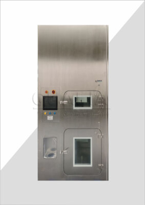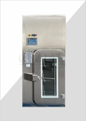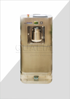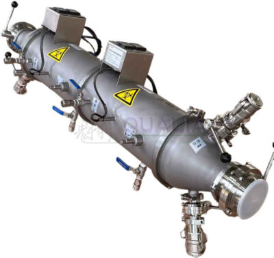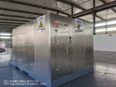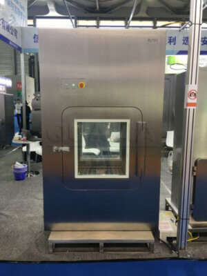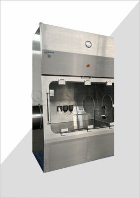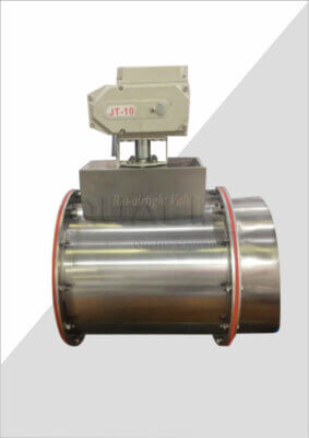

Selecting Vacu-Pass materials for a decontaminated boundary is two separate decisions made on one assembly: the chemical resistance of every exposed surface to the actual decontamination agent and exposure conditions, and, where the project specifies it, the electromagnetic function of the penetration and its connections. Neither answers the other. The conditions that decide the first are the agent and its formulation, concentration, contact time and frequency, and which components sit inside the exposure boundary; the conditions that decide the second are the shielding and bonding requirements the electrical specification sets and the components and connections it covers. A Vacu-Pass cord and cable port is a sealed penetration that lets instrument and power cables cross a laboratory boundary without defeating it, so the sealing elements themselves become wetted surfaces during fumigation or surface cleaning.
Map exposed materials and decontamination conditions
Start with a component schedule rather than a material name. List the sleeve or body, the sealing elements, the exposed cable jackets passing through the port, any surface finish or coating, and the joints and sealants at the wall interface, then write against each one the cleaning or fumigation exposure it will actually see in service.
A single material label cannot describe every contact surface in an assembled cable penetration. The port body may be one material, the compression or gland seal another, the cable jacket a third chosen by whoever supplied the instrument, and the perimeter sealant a fourth specified by the wall contractor. Vaporized hydrogen peroxide reaches all of them if they are on the room side of the boundary; a liquid sporicide applied by wiping may reach only the exposed face. Those are different exposures and they belong in different rows of the schedule.
The exposure side of the schedule needs the same detail as the component side. Name the agent and its formulation, the concentration and contact time, whether exposure is a routine surface clean or a whole-room gassing, and how often each occurs over the service life. Cumulative exposure matters for elastomers, where repeated oxidative cycles change compression set and surface condition long before a single cycle would.
Exclude parts that are demonstrably outside the exposure boundary instead of assuming the whole assembly sees the same agent. A cable jacket on the clean corridor side of the wall, or a clamp buried in the wall construction, may carry no decontamination duty at all. Say so explicitly in the schedule, with the reason, because that exclusion is itself an assumption someone will need to check during installation when the actual penetration geometry is known.
Screen compatibility evidence for the actual formulation
Compatibility evidence is only useful when its formulation, agent and exposure conditions match the proposed use, so screen each document against those three variables and record where they diverge. A silicone elastomer tested against 35 percent hydrogen peroxide solution is not evidence for a vaporized hydrogen peroxide cycle; a result for one peracetic acid blend is not a result for another with different stabilizers and surfactants. The gap, once identified, is a defined question for representative assessment rather than a vague doubt.
General design guidance frames the problem without resolving it. The Swiss Expert Committee for Biosafety’s recommendation on structural and technical safety measures in BSL-3 laboratories treats the chemical resistance and porosity of sealing materials as design concerns for a penetration boundary intended to be fumigated, which is why both properties belong in the schedule. That nonbinding Swiss recommendation supplies no Vacu-Pass-specific compatibility result, and a qualified formulation, a service life or a decontamination outcome cannot be inferred from it.
Porosity deserves separate attention from chemical resistance because they fail differently. A material can be chemically stable in a given agent and still hold contamination in surface voids, or craze and roughen after repeated cycles so that a surface which was cleanable at handover no longer is. The CDC/NIH BMBL, sixth edition, describes sealed cleanable laboratory surfaces and whole-laboratory decontamination provisions selected by risk assessment; it is US advisory guidance, its BSL-3 and suit-facility provisions differ in scope, and local rules together with the facility risk assessment decide what applies to a given penetration.
Where the evidence gap cannot be closed from existing documents, the practical options are a representative assessment on the actual formulation and components, or a documented change to the agent or the material. Which is acceptable, and what counts as representative, is set by the project’s approved procedure and its designated approver, not by the material supplier.
Define the separate electromagnetic interface requirements
Where the project specifies electromagnetic-interference control, write that requirement separately from the penetration sealing requirement and name the components and connections each one covers. The sealing requirement concerns which surfaces resist the agent and how the boundary stays intact; the electromagnetic requirement concerns shielding continuity, cable screen termination, bonding to the building ground system and any attenuation performance the electrical team has specified.
The two requirements can be satisfied by different parts of the same assembly, which is why they must be written out individually. A chemically suitable sealing element leaves the electromagnetic function unanswered, and an electrical specification that calls for a conductive path and bonded termination says nothing about whether the exposed materials survive repeated gassing cycles. Treating one as evidence for the other is how an assembly passes a submittal review and then fails a site test.
Define the scope boundaries explicitly: which components carry the shielding duty, where the screen is terminated, what the bonding connection attaches to, and who owns the connection on each side of the wall. UFGS 01 33 00, a US editable guide specification for submittal procedures, gives one documentation example of configuration-specific product identification and documented interfaces with other trades; it is not a universal requirement, and it demonstrates no product compatibility, geometry or installed performance.
If the project documents contain no electromagnetic requirement, the penetration is a sealing and containment component and nothing more. Do not write a shielding claim into the specification to fill the silence; an invented requirement commits the project to a verification nobody asked for and can push the material selection away from the chemical duty that does exist.
Compare complete assemblies against both duties
| Assembly check | What to compare | What leaves the decision unresolved |
|---|---|---|
| Decontamination suitability | Exposed component identities and chemical-resistance evidence matched to the formulation, agent and exposure conditions | General guidance or evidence for a different formulation or exposure does not establish compatibility for the proposed components. |
| Electromagnetic function, where specified | Shielding and bonding requirements, the components and connections they cover, and any explicitly justified separate shielding interface | A chemically suitable material does not establish the required electrical function; the proposed electrical interface still needs applicable support. |
| Evidence for the submitted assembly | Certificates, data sheets or assessments matched to the identified components, installation and claimed functions | A generic document cannot resolve a claim outside its scope; missing assembly-specific support remains an evidence gap. |
Compare whole proposed assemblies against the exposure schedule and the electrical interface specification together, rather than choosing between materials by a metal-versus-polymer label. The question is how an assembled set of components meets two duties at once, and the same polymer that gives a compliant seal under repeated vaporized hydrogen peroxide exposure may carry no shielding function, while a conductive metal body may provide an excellent bonded path and still rely on an elastomeric seal whose compatibility is the open item.
The functional difference behind that is straightforward. A seal works by conforming to surfaces under compression and holding that conformity through thermal and chemical cycling, which favors elastomers with the right compression set and chemical stability. A shield works by presenting a continuous conductive enclosure with low-impedance terminations, which favors metals and conductive gaskets and depends on joint design and bonding rather than bulk material alone. An assembly can combine both, but only if the designer says which component performs which function and how the conductive path crosses the sealing element.
Treat an explicitly justified separate shielding interface as a different comparison case. If the electrical team accepts shielding continuity established outside the penetration itself, the port is relieved of the electromagnetic duty and the comparison collapses to chemical suitability and sealing performance. That justification belongs in the project record, with the reason and the interface location stated, because it changes which assemblies are eligible.
Consider an illustrative case, assuming a BSL-3 room decontaminated routinely by vaporized hydrogen peroxide and an instrument cable requiring a terminated screen. Two assemblies may both look acceptable: one with a polymer body and a seal of known resistance but no conductive path, one with a metal body and bonded gland but a seal of unverified formulation. Neither is ready for selection; one needs a documented shielding interface or a different body, the other needs compatibility evidence matched to the actual agent. Naming which item is missing for each candidate is more useful than ranking the two.
Control evidence gaps and later material substitutions
A generic certificate or material data sheet is useful only once it is matched to the submitted component identity, the function being claimed and the scope of the evidence it actually carries. Check that the document names the same formulation and grade as the submitted part, that the test condition corresponds to the exposure in the schedule, and that the claimed function, whether chemical resistance, surface cleanability or electrical bonding, is the one the document tests. Where the match fails, the missing assembly-specific support is a defined request to the supplier rather than a reason to downgrade the whole submission. A directly applicable verified assessment can be used within its actual limits after project review.
Material substitutions late in a project reopen both duties, even when only one appears affected. Changing a seal compound for availability can alter the compression behavior at a bonded joint and therefore the shielding termination; changing a body material for cost can change the chemical exposure picture for the seal it compresses. Track the replaced components, the exposure assumptions that applied to them and the electrical connections they carried, and assess containment and electromagnetic implications before carrying over previous acceptance evidence. The verification and release needed for a given modification are defined by the responsible project team under the project’s approved procedure.
Record the gaps that remain open at award, each with its owner and the evidence that would close it, so they do not reappear as site questions during commissioning. A gap with a named owner and a defined test is manageable; an unrecorded assumption about which seal saw which agent is not.
Before approaching a supplier, have the component schedule with exposure conditions, the decontamination agent formulation and cycle description, the electrical interface specification with its shielding and bonding scope or a clear statement that none applies, the wall construction and penetration geometry, and the list of evidence the project will require for each claim. With those in hand, the discussion about Vacu-Pass materials, decontamination and EMI becomes a review of specific component identities against specific duties rather than an exchange of general material names.
Frequently Asked Questions
Q: Does every part of a Vacu-Pass installation need evidence for the same decontamination exposure?
A: No. Match each component to the exposure it will actually encounter, including the sleeve, seals, exposed cable jackets, finishes and joints. A part can be excluded from a particular exposure assessment only when its position outside that exposure boundary is documented; do not assume all parts have identical contact conditions.
Q: Should I choose a metal or polymer version before defining the project requirements?
A: No. A material name alone cannot settle the choice. First establish the decontamination agent and exposure conditions, then any required shielding and bonding interfaces. Compare the proposed combinations of components against those requirements rather than treating metal or polymer as a universal indicator of suitability.
Q: Do I need electromagnetic-performance evidence when the project only specifies decontamination?
A: A decontamination requirement alone does not establish an electromagnetic requirement. Confirm whether the electrical specification includes shielding or bonding duties for the penetration and its connections. If it does not, keep the selection focused on the documented project requirements without adding an unsupported shielding claim.
Q: Can an approved material assessment be carried over when a seal or cable is replaced?
A: Not automatically. Identify the replacement component and check whether the exposure assumptions, material formulation or relevant electrical connections have changed. Reassess the affected decontamination and electromagnetic evidence before carrying over the earlier acceptance; the responsible project team determines the verification and release needed for the modification.