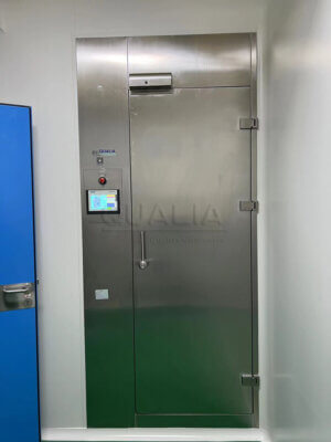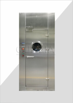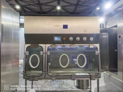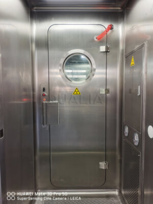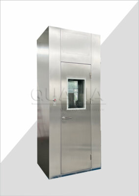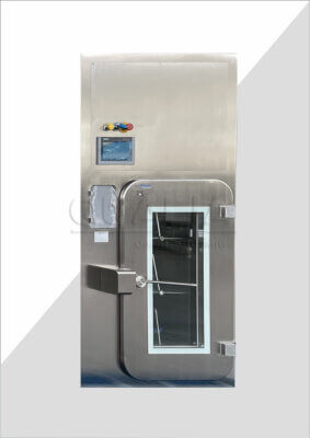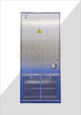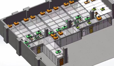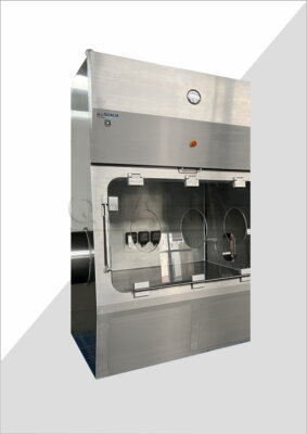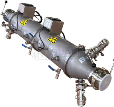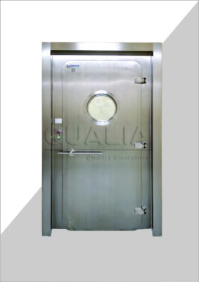

A material transfer point that crosses a pressure boundary cannot be retrofitted the way a standard utility tie-in is handled, because the boundary itself is the function being protected during the work, not just around it. The question the project team has to answer before any cutting starts is not whether the new transfer equipment will work, but whether the route, the boundary, and the surrounding room relationships can be opened, modified, and closed again without an undocumented gap at any point in the sequence.
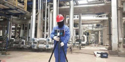
Survey the existing route, pressure boundary, services, and access
| Survey stream | Field question | Retrofit decision supported |
|---|---|---|
| Route and structural opening | Do the observed route and opening conditions match the as-built information? | Define the physical scope of the new transfer point and any cut into the existing boundary. |
| Pressure boundary | What pressure relationships exist across the affected route? | Identify the room relationships that the retrofit may change and must later requalify. |
| Utilities and controls | Which services and control interfaces are present in the field? | Define the affected integration and shutdown scope. |
| Maintenance access | What access is available around the proposed transfer point? | Confirm that the design can provide safe maintenance access. |
Retrofit design decisions depend on field conditions, not on what the original drawings say. As-built documentation describes the route, pressure relationships, utility runs, and structural openings as they were designed or last recorded, but modifications, repairs, and incremental changes made after commissioning are not always reflected in that documentation. Where the gap between record and field condition is large, a design built on the record alone risks specifying a transfer point that cannot be installed as drawn, or that misreads the pressure relationships it is meant to preserve.
The pressure boundary is the central fact the survey has to establish, because the retrofit’s entire justification rests on maintaining or improving the relationships that already exist between the spaces the route connects. A transfer point that looks identical in two projects can sit in entirely different pressure contexts: one adjoining a space held at positive pressure to protect a process, another adjoining a space held at negative pressure to contain a hazard. The survey has to identify which relationship applies at the specific route under review, because the retrofit design, the temporary containment plan, and the eventual requalification all follow from that relationship, not from the transfer technology alone.
Utilities and control interfaces present in the field — power, controls wiring, building management connections, any exhaust or drainage already serving the area — define how much of the existing infrastructure the retrofit will touch versus how much new infrastructure it introduces. A route with minimal existing services simplifies the shutdown scope; a route already carrying multiple integrated services expands it, because each one becomes a dependency the cutover sequence has to account for.
Maintenance access is easy to treat as a downstream installation detail, but it is a design input. If the field survey shows that the only feasible position for the new transfer point compromises access for routine servicing, that conflict needs to surface before design commitments are made, not after installation, when correcting it would mean reopening the boundary a second time.
Define the cutover boundary and temporary containment for construction
Once the survey establishes what exists, the project has to define what separates the construction work from the still-operating facility around it. This is a different boundary from the final transfer-point boundary the retrofit is building toward — it is a temporary one, scoped specifically to the duration of construction, and it has to hold even while the permanent boundary is partially disassembled.
The core difficulty is that the retrofit necessarily creates a period during which the existing boundary is incomplete: an opening exists, equipment is partially installed, and the pressure or containment relationship the original design relied on is not yet restored. Temporary segregation exists to substitute for that missing boundary function for as long as the condition lasts. Where the facility’s pressure relationship is protecting product rather than operators, the temporary containment emphasizes excluding contamination from the open route. Where the relationship is protecting operators or the environment from hazardous material inside the space, the temporary containment emphasizes preventing escape from the open route. The physical construction of a barrier may look similar in both cases, but the direction of the risk it is holding back is not, and that difference should shape where monitoring points, access controls, and work permits are placed relative to the opening.
A work permit tied to a cut into the existing boundary is not a formality separate from the engineering plan; it is the mechanism that connects the physical opening to the administrative control confirming that temporary segregation is in place before the cut is made and remains in place until the opening is closed or the permanent interface is installed. Treating the permit as sequential with the physical work, rather than parallel to it, is what keeps the two from drifting apart during a multi-stage installation.
The scope of temporary containment also depends on how much of the surrounding area the retrofit affects. A transfer point replacement confined to a single wall penetration asks less of the temporary boundary than a retrofit that also touches adjoining utilities or structural elements, because each additional affected element is a potential path around the temporary containment rather than through the monitored opening.
Sequence shutdown, decontamination, openings, installation, and restart
| Stage | Boundary-control decision before advancing |
|---|---|
| Shutdown | Define the planned shutdowns that apply before work begins at the existing boundary. |
| Cleaning or decontamination | Define the applicable cleaning or decontamination for the isolated work zone. |
| Boundary opening | Match every cut into the existing boundary to temporary segregation and a work permit. |
| Installation | Keep the transfer-point work within the defined cutover boundary while the applicable interfaces are installed. |
| Restart | Recommission the affected interlocks, alarms, airflow or pressure relationships, and transfer cycles before route release. |
The sequence of a boundary retrofit is not an administrative checklist; it is the mechanism that keeps the facility’s protection function intact at every stage of a process that necessarily passes through a stage where it is not intact. Each stage in the sequence exists to close out the risk introduced by the stage before it, so skipping or compressing a stage does not just save time, it removes the control that the following stage assumes is already in place.
Shutdown defines what has to stop operating before work begins at the existing boundary, and its scope depends on what the survey identified as connected to the affected route. A route with an isolated utility footprint allows a narrower shutdown; a route integrated into shared systems may require a broader one, because those systems cannot be safely opened while still serving operating areas.
Cleaning or decontamination addresses the isolated work zone itself, and what it needs to address depends on what the space was used for and what the original pressure relationship was protecting. A zone that was protecting a product requires a different decontamination logic than a zone that was containing a hazard, even though both are being prepared for the same category of physical work.
The boundary opening stage is where the temporary containment plan is tested in practice: every cut has to correspond to an already-defined segregation and permit, not to one generated after the fact to match work already underway. Installation then proceeds inside that temporary boundary, and its scope should stay within what the boundary was designed to hold — if the installed configuration changes during the work in a way that extends beyond the original temporary containment plan, that plan needs to be revisited before continuing, not adjusted informally in the field.
Restart is where the sequence turns from construction logic back to operating logic. Recommissioning the interlocks, alarms, airflow or pressure relationships, and transfer cycles affected by the work is what confirms the boundary has been restored, and the scope of that recommissioning should match the actual changes made, not a generic checklist carried over from the original commissioning.
Integrate doors, controls, alarms, utilities, exhaust, and drainage
| Retrofit interface | Integration question | Applicability boundary |
|---|---|---|
| Doors and transfer controls | How will the new transfer point integrate with door logic and transfer controls? | Material-airlock interlocks are relevant where the sterile-manufacturing context applies. |
| Room pressure monitoring and alarms | How will the modified route connect to pressure monitoring, and which affected alarms must be recommissioned? | Critical-pressure monitoring requirements depend on the applicable facility context. |
| Fire and building interfaces | Which fire and building interfaces are affected by the new transfer point or boundary opening? | Review only the interfaces touched by the actual change. |
| Utilities | Which field-verified services must be integrated with the transfer point? | The scope follows the utilities present in the existing route and the selected configuration. |
| Exhaust and drainage | Does the selected transfer-point configuration require either interface? | Integrate exhaust or drainage only where applicable. |
| Maintenance access | Does the installed configuration retain safe access for maintenance? | Check access against the final transfer-point arrangement. |
A new transfer point is rarely a standalone device; it becomes one more node in a network of door logic, pressure monitoring, alarms, and building interfaces that already governs the surrounding space. The integration question for each of these systems is distinct, and treating them as a single combined task tends to leave at least one connection unverified.
Door and transfer controls have to coordinate with whatever logic already governs adjoining doors, so that the new point does not create a condition the existing logic did not anticipate — for instance, a transfer path that could be opened simultaneously with another opening the original design assumed would stay mutually exclusive. Where the broader context is sterile manufacturing, material airlock interlocks and transfer controls described in EU GMP Annex 1 become a relevant reference point for how interlocking and monitoring are expected to function, though their applicability to a containment-oriented retrofit depends on whether that sterile-manufacturing context actually governs the space in question.
Room pressure monitoring has to extend to cover the modified route, and the alarms tied to that monitoring need to be identified specifically — not assumed to already include the new point by virtue of being part of the same system. Fire and building interfaces affected by the opening or the new transfer point deserve the same specific identification rather than blanket assumption, because a retrofit that changes a structural opening can affect fire-rated assemblies or building systems that had no prior relationship to the transfer function itself.
Utilities integrated at the transfer point follow directly from what the field survey found already present, plus whatever the selected transfer configuration requires beyond that. Exhaust and drainage are not universal requirements — whether either applies depends on the selected transfer-point configuration and what it handles, and integrating either one where the configuration does not call for it adds complexity without a corresponding function.
Maintenance access, raised during the survey as a design input, resurfaces here as a verification point: the installed configuration needs to be checked against the access the design intended, because construction sequencing and field conditions can erode access that the original drawings preserved.
Requalify every function and room relationship changed by the retrofit
| Changed item | Verification focus | Scope boundary |
|---|---|---|
| Door or transfer interlocks | Recommission the affected interlock functions after installation. | Include only interlocks affected by the retrofit. |
| Alarms | Recommission the alarms affected by the changed transfer point or controls. | The alarm scope follows the actual control changes. |
| Airflow or pressure relationships | Verify the room relationships affected by the new opening and transfer route. | Acceptance values must come from the applicable project and facility requirements. |
| Transfer cycles | Recommission the transfer cycles affected by the installed configuration. | The cycle scope follows the selected transfer technology and actual changes. |
| Biocontainment functions | Perform documented verification where changes, repairs, or modifications may affect biocontainment. | Containment-level and activity-specific requirements must be established for the project. |
Requalification scope should be derived from what changed, not assumed from a standard checklist carried over from the facility’s original qualification. A retrofit that touches one door and one utility connection does not require the same verification scope as one that reconfigures multiple room relationships, and sizing the requalification to match the actual change is what keeps the verification effort proportional to the risk introduced.
Door or transfer interlocks need recommissioning scoped to the interlocks actually affected by the installation — not the full interlock inventory of the room, unless the retrofit’s reach extends that far. The same logic applies to alarms: the alarm scope follows the control changes made, so an alarm unrelated to the modified transfer point or its controls does not need to be re-verified solely because it shares a panel with one that does.
Airflow or pressure relationships affected by the new opening and transfer route require verification against acceptance values appropriate to the applicable project and facility requirements — the retrofit does not get to default to generic values borrowed from an unrelated project or guideline. ISO 14644-4:2022 addresses verification and life-cycle maintenance considerations for modified cleanrooms through design, construction, and start-up, offering a framework for how that verification fits into the lifecycle, without prescribing a specific technology or acceptance threshold that would apply uniformly across projects.
Transfer cycles themselves need recommissioning matched to the selected transfer technology and to the actual changes made during the retrofit, since a transfer cycle’s qualified parameters are specific to the equipment and configuration installed, not to the category of transfer point in general.
Where biocontainment functions are part of what the retrofit affects, the Canadian Biosafety Standard, Third Edition calls for documented verification after changes, repairs, or modifications that may affect biocontainment — a principle that applies within its stated containment-level and activity-specific framework, which means the specific requirements still need to be established against the containment level and activity actually governing the space, rather than generalized from the standard’s existence alone.
Release the route after deviation closure and operating handover
Releasing the route back into operation is a distinct decision from completing the physical and verification work, because it depends on whether every deviation opened during the retrofit has been formally closed, not merely whether the equipment is installed and functioning. A deviation opened during an unexpected field condition, a sequence adjustment, or a verification result outside the expected range represents an open question about the boundary’s integrity until it is resolved and documented, regardless of how minor the underlying issue turns out to be.
Operating handover is where the retrofit’s documentation has to align with how the route will actually be used and maintained going forward — updated procedures, updated control logic references, and updated maintenance access information all need to reflect the as-installed condition rather than the original design intent, since the gap between the two is exactly what prompted the field survey at the start of the project.
The sequence of closure and handover matters: releasing the route before every deviation tied to boundary integrity is closed reintroduces the same risk the temporary containment plan was built to manage, just without the construction-phase controls still in place to catch it. Where the retrofit touched a single, contained function, closure and handover can proceed in a straightforward sequence. Where it touched multiple interlocked systems or room relationships, closure may depend on confirming that each affected function was independently verified before the route as a whole is considered ready for return to service.
The information the project supplies about what was actually changed — not just what was planned — is what allows a supplier reviewing the project, including the configuration and quotation review conducted by Qualia, to confirm which interfaces and functions require attention as part of that specific scope, rather than applying a generic assumption about what a transfer-point retrofit typically involves.
Frequently Asked Questions
Q: Can the retrofit be designed from as-built drawings alone?
A: No. Verify the route, structural opening, pressure relationships, utilities, controls, and maintenance access in the field before fixing the design. Record any mismatch because it can change the opening, integration, shutdown, and requalification scope.
Q: How should the team decide what can remain operational during the retrofit?
A: Define the isolated work zone and trace every planned boundary cut to its temporary segregation, shutdown, cleaning or decontamination step, and work permit. Any operation outside that zone should be assessed against the pressure relationships, services, and controls that the work may affect.
Q: What should be settled before choosing between a biosafety pass box, dunk tank, or VHP pass box route?
A: First define the required transfer process, material flow, boundary conditions, transfer cycle, and available interfaces. Then compare each configuration against door logic, monitoring, utilities, maintenance access, and any applicable exhaust or drainage requirement rather than choosing from the opening size alone.
Q: Does a new transfer point require the entire facility to be requalified?
A: The verification scope should follow the actual changes. Identify every affected interlock, alarm, airflow or pressure relationship, transfer cycle, and biocontainment function, then apply the project-specific acceptance requirements to those items before releasing the route.