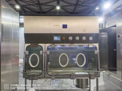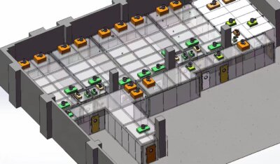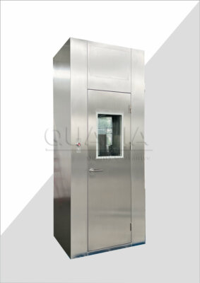

An isolator design review depends on utility and interface decisions that are finalized long before the equipment reaches the room, yet those decisions determine whether the installed unit will actually function as intended inside that room. The question is not whether the isolator meets its own design specification, but whether the room, the controls architecture, and the facility services around it have been defined to match it. Getting this wrong surfaces at installation or qualification, when changes are harder and more disruptive to make.
Process Load and Room Data Needed Before Interface Review
Before any interface can be reviewed meaningfully, the room and process data that the isolator will operate against need to be established. This is not a formality — it is the basis against which every subsequent utility, control, and access decision gets judged. Without defined process loads, room pressure cascades, and ambient conditions, a supplier and a facility team are each working from assumptions that may not match.
The process load determines what the isolator needs from the room: how much heat it rejects, what exhaust and supply volumes it requires, and what pressure differential it must sustain against adjoining spaces. Room data determines what the room can actually deliver: available supply and exhaust capacity, existing pressure cascade logic, structural and spatial constraints, and the control system the isolator must integrate with. Where either side of this exchange is incomplete, the interface review becomes a negotiation conducted without reference points, and resolving mismatches later costs more than defining them correctly at the outset.
A critical point that often gets underweighted is that process and room conditions are not static. An isolator operates in multiple modes — normal processing, standby, cleaning, bio-decontamination, alarm, and shutdown — and each of these can carry a different demand profile. A unit that draws a given exhaust volume during normal operation may require a materially different exhaust or pressure response during a bio-decontamination cycle, and the room’s air handling and pressure cascade need to accommodate that range, not just the steady-state condition. If the room design is based only on normal-operating assumptions, the interface will be undersized or mismatched the moment the isolator shifts into another mode.
This is also where responsibility for providing accurate data needs to be settled early. The facility side needs to supply confirmed room pressure targets, available utility capacities, and structural constraints. The process side needs to supply confirmed product and process requirements, including any mode-dependent variation. Where this exchange happens late, or where one side assumes the other has already accounted for mode changes, the interface review inherits that gap and the mismatch is discovered only when the installed condition is tested against real operating states rather than design assumptions.
Supply, Exhaust, Pressure, and Heat-Rejection Boundaries
| Room interface | What to confirm | Project-specific decision |
|---|---|---|
| Supply | Demand and boundary conditions in each applicable operating, standby, cleaning, bio-decontamination, alarm, and shutdown state | Supply interface point and room-side provision |
| Exhaust | Exhaust demand, connection location, and route in each applicable state | Exhaust boundary and its coordination with the room design |
| Pressure interaction | How applicable operating and shutdown states interact with the room pressure boundary | Accepted pressure boundary and required control-system handshake |
| Heat rejection | Heat load in each applicable state and the planned rejection path | Heat-rejection basis to carry into the room design |
Once process and room data are established, the specific environmental interfaces — supply, exhaust, pressure, and heat rejection — need to be checked individually, because each behaves differently and each can expose a different mismatch between isolator and room.
Supply and exhaust are often treated as a single balanced pair, but their boundary conditions do not always move together. A change in exhaust demand during one operating state does not necessarily produce a proportional change in supply demand, particularly where bio-decontamination or alarm states introduce transient demand spikes. The room-side air handling system needs to be evaluated against the full range of states the isolator can enter, not only the condition that applies during normal production. Where the room’s air handling capacity has been sized only for steady-state operation, a mode transition can create a pressure or flow condition the room was never designed to absorb.
Pressure interaction is the area where isolator and room design most directly depend on each other. The isolator’s internal pressure strategy — whether it operates at positive or negative pressure relative to the room, and how that differential is maintained — has to be compatible with the room’s own pressure cascade. A room designed around one pressure logic cannot simply accept an isolator built around a different one without a control-system handshake that reconciles the two. This handshake needs to be defined for every applicable state, including shutdown, since a loss of power or utility can change which side of the boundary is maintaining differential pressure.
Heat rejection is frequently the interface that receives the least attention until late in a project, yet it directly shapes mechanical and electrical room design. An isolator’s heat load changes with operating mode, and the planned rejection path — whether through room air handling, a dedicated cooling circuit, or another mechanism — has to be sized against the highest load condition the isolator will produce, not an average. Where heat rejection is undersized relative to peak conditions, the consequence surfaces as instability in maintaining the process environment rather than as an isolated mechanical fault, which makes it harder to diagnose after installation than it would have been to catch during design review.
Each of these four boundaries needs a confirmed, project-specific decision rather than a general assumption, because the isolator’s suitability for a given room depends on how these interact, not on any one of them in isolation.
Power, Controls, Alarms, Network, and Data Responsibilities
Electrical and controls interfaces raise a different kind of question from the environmental ones: not how much capacity is needed, but who is responsible for providing, integrating, and maintaining each connection and signal. Power supply, control signals, alarm outputs, network connectivity, and data handling each cross a boundary between the isolator, the facility’s electrical and controls infrastructure, and in some projects a separate building management or SCADA system.
The consequence of leaving this boundary undefined is not usually a technical incompatibility — most signals and protocols can be matched given enough coordination — but a gap in accountability. If no single list assigns each power feed, control signal, alarm point, and data interface to the isolator supplier, the facility contractor, the controls integrator, or the buyer directly, items get assumed into someone else’s scope and are discovered missing only during commissioning. Alarm handling is a specific case worth separating out: an isolator’s internal alarm logic needs to interface with the facility’s alarm and monitoring system in a way that preserves the intended response, and that handshake has to be agreed before installation, not inferred from each party’s standard practice.
Network and data responsibilities add another layer, particularly where the isolator’s control system needs to exchange data with a plant historian, a building management system, or a validation data repository. The physical network connection is only part of this; data format, access rights, and who maintains the integration over the equipment’s life also need to be assigned. Where this is left informal, maintenance of the interface after commissioning can become unclear, since the party who configured it originally may not be the party responsible for keeping it functional as either the isolator’s software or the facility’s systems are updated.
Building a single interface list that assigns every applicable utility and signal to a named party — isolator supplier, facility contractor, controls team, or buyer — is the practical mechanism for closing this gap. The same list approach that applies to supply and exhaust applies here: each item needs an owner, a defined state-by-state behavior where relevant, and a point of agreement before the room design is finalized.
Gases, Drains, VHP, and Other Service Connections
Service connections beyond power and air handling — process gases, liquid drains, and connections for VHP delivery where bio-decontamination is part of the isolator’s function — each introduce their own location, routing, and compatibility questions that need resolution during interface review rather than after installation.
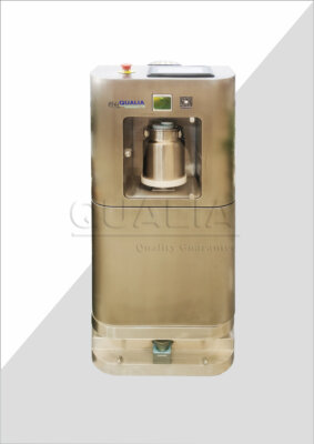
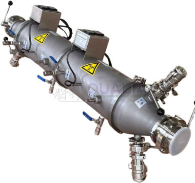
Gas connections require agreement on connection location, line routing, and the isolation points needed for maintenance or emergency shutdown. Drain connections raise a related but distinct question: routing has to account for the isolator’s physical position in the room and for any containment or decontamination requirement that applies to what passes through the drain, which can affect whether a direct connection is appropriate or whether an intermediate treatment step is needed. Where the isolator’s function includes VHP-based bio-decontomination, the VHP transfer and decontamination equipment interface needs particular attention, since VHP generation, delivery, and aeration each impose their own connection and routing requirements that are distinct from the isolator’s general air handling interface, and the equipment providing that function needs to be specified by its own role and connection points rather than assumed as part of the isolator’s general utility package.
Each of these connection types shares a common design logic: the location and routing agreed during interface review determines whether the connection can be made without later disruption to the room or to the isolator’s structure, and whether isolation points exist where they will be needed for maintenance. A connection whose location was never confirmed against the as-built room drawing risks being inaccessible, or risks requiring rework in a space that is far harder to modify after the isolator is installed than before.
The categories of service connection a given project requires depend entirely on the isolator’s function. A unit without a bio-decontamination cycle has no VHP interface to resolve; a unit processing certain gases will need isolation and venting considerations that a unit without that process load does not. The interface review needs to start from the isolator’s actual function and process requirements rather than from a generic checklist, so that the connections reviewed match what the installed equipment will actually need.
Maintenance Clearances, Shutdown Routes, and Installation Access
| Access check | What to confirm | Design decision informed |
|---|---|---|
| Installation route | The equipment route and applicable service-connection routes fit the room design | Whether the planned installation path supports the approved connection locations |
| Maintenance clearance | Service clearances are included around the applicable connection and maintenance points | Whether the room layout provides the required maintenance access |
| Isolation points | Locations and access for applicable utility isolation points | Whether isolation can be included in the shutdown and maintenance plan |
| Shutdown interfaces | Utility, alarm, and control boundaries that change in alarm or shutdown states | Which isolation points and control-system handshakes require agreement |
| Future replacement access | The future removal and replacement route is included in the room review | Whether replacement access is preserved in the room design |
Interface review that stops at commissioning readiness misses a category of decision that affects the isolator across its service life: whether the room design preserves the physical access needed to install, maintain, isolate, and eventually replace the equipment.
Installation access is the first of these, and it needs confirmation before the room design is finalized rather than after, because the isolator’s physical route into its final position — and the routes for the service connections that follow it — have to be compatible with the room’s doorways, corridors, and any lifting or rigging constraints. A room designed without reference to the isolator’s actual dimensions and installation sequence risks a mismatch that is far more expensive to resolve once walls, doors, or adjacent equipment are in place.
Maintenance clearance is a related but ongoing concern: the space required around service and connection points for routine maintenance needs to be built into the room layout, not treated as available by default. Where clearance is insufficient, maintenance tasks that would otherwise be routine become constrained, and the practical effect is that maintenance takes longer or requires partial disassembly of surrounding infrastructure to gain access.
Isolation points — the locations where utilities can be shut off or disconnected for maintenance or in a shutdown condition — need to be both physically located and accessible in a way that supports the facility’s maintenance and emergency procedures. This connects directly to the operating-mode logic described earlier: the utility, alarm, and control boundaries that apply in an alarm or shutdown state determine which isolation points need to be reachable without delay, and the room design needs to reflect that rather than placing isolation points behind equipment or in locations that are only accessible during a planned outage.
Future replacement access is the clearance category most often deferred, since it does not affect initial installation or near-term maintenance. But an isolator has a finite service life, and the room design decision that accommodates installation does not automatically accommodate removal and replacement years later, particularly if adjacent equipment, walls, or services have been added in the interim. Confirming that a replacement route exists — and preserving it rather than allowing it to be built over — is a decision made during the original room design, not something that can be retrofitted once the surrounding space has filled in.
Responsibility Matrix and Installed-Condition Acceptance Checks
| Review point | Evidence to check | What the evidence does not establish by itself |
|---|---|---|
| User requirements and design qualification | Traceability from approved user requirements to the design and its interface decisions | Final installed suitability when project-specific utilities and criteria remain unresolved |
| Factory and site acceptance testing | A defined distinction between factory acceptance evidence and site acceptance evidence | That factory evidence alone is suitable for the installed site |
| Installation qualification | Verification of the installed condition, including applicable drawings, utilities, calibration, and as-built checks | Operational performance under the defined challenge conditions |
| Operational qualification | Challenge testing against predefined acceptance criteria | Suitability beyond the project-specific conditions and criteria that were tested |
| Final evidence review | Supplier evidence reviewed against site suitability and the approved project criteria | An unconditional conclusion for utilities, stages, or criteria that were not defined for the project |
Bringing these interface decisions together into a single responsibility matrix is what allows a project team to verify, rather than assume, that every utility, signal, and access point has an assigned owner and a defined acceptance path. This matrix is the practical companion to the installed-condition checks that follow, since it determines who is accountable for providing the evidence each check requires.
The acceptance sequence has distinct stages, and each produces evidence that answers a different question. Traceability from approved user requirements through design qualification establishes that the interface decisions made during design review were captured correctly, but this traceability does not by itself confirm that the installed condition matches the design, particularly where project-specific utilities or acceptance criteria remained unresolved at the point of design approval. Factory and site acceptance testing are distinct for a related reason: factory testing verifies the isolator against its own specification under factory conditions, while site acceptance testing verifies behavior once the unit is connected to the actual room utilities and controls, and evidence from the factory stage does not establish that the installed, site-connected condition performs the same way.
Installation qualification addresses the installed condition specifically — verifying drawings, utility connections, and calibration against the as-built state — and is a necessary step for confirming that the interfaces reviewed earlier were actually implemented as agreed. This stage is explored in more detail in the context of drawings, utilities, calibration, and as-built checks for containment equipment, but its role here is to confirm installation, not operational performance under process conditions. Operational qualification follows, challenging the installed isolator against predefined acceptance criteria tied to its defined operating modes; this confirms performance under the specific conditions tested, not suitability beyond the project-specific conditions and criteria that were part of that test plan. Annex 15 to EudraLex Volume 4 frames this progression — URS and design qualification traceability, the FAT/SAT distinction, installation verification, and challenge testing against predefined acceptance criteria — while making clear that the exact stages, utilities, and criteria applied are project-specific and require a site-suitability review rather than a generic conclusion. ISO 14644-7, which addresses separative devices including isolators, frames design, construction, installation, test, and approval as a customer-supplier requirement exercise, but it does not specify the application utilities or the process running inside the device, which is why the responsibility matrix and project-specific interface list carry weight that the standard itself does not supply.
A supplier responsibility matrix for a project of this kind typically distinguishes buyer, EPC, and vendor boundaries explicitly, since ambiguity in any one of these roles is what produces gaps between design intent and installed condition. The information a buyer supplies about process loads, operating modes, and room constraints enters a supplier’s configuration and quotation review as the basis for how the isolator’s utility and interface specifications are set, which is why establishing that information early, and keeping it consistent through each acceptance stage, is what allows the final evidence review to close out against the approved project criteria rather than leaving gaps that surface only once the equipment is in service.
Frequently Asked Questions
Q: What should be resolved before approving the isolator utility interfaces?
A: Confirm the applicable utility and signal list, connection locations, room-side provisions, control handshakes, and responsible party for each interface. Any unresolved exhaust, pressure, heat-rejection, access, or acceptance boundary should remain visible as a project decision rather than being treated as approved.
Q: How should utility requirements be documented when isolator demand changes by operating mode?
A: Record the demand and boundary conditions for each applicable operating, standby, cleaning, bio-decontamination, alarm, and shutdown state. Use those state-specific entries to coordinate supply, exhaust, pressure interaction, heat rejection, alarms, and isolation points with the room design.
Q: Who should own an isolator utility or control interface?
A: Assign each applicable utility and signal in one interface list to the isolator supplier, facility contractor, controls team, or buyer. The assignment should cover both the physical provision and the related connection, control, alarm, or shutdown responsibility so that no boundary is left implied.
Q: Is factory acceptance evidence enough to approve the installed isolator?
A: No. Factory and site acceptance evidence should remain distinct, and supplier evidence must be reviewed for suitability at the installed site. Installation verification and operational challenge testing should then be judged against the project’s approved requirements and predefined acceptance criteria.
Q: What access information should be checked alongside the utility design?
A: Check the equipment installation route, service-connection routes, maintenance clearances, accessible isolation points, shutdown interfaces, and future removal path in the same review. This shows whether the planned room layout can support installation, servicing, isolation, and eventual replacement without relying on an unconfirmed route.