
A load moving from a biosafety boundary into an aseptic-processing area, or the reverse, crosses two different protection objectives that do not automatically recognize each other’s controls. Containment logic exists to keep hazardous material inside a boundary; aseptic logic exists to keep contamination out of a product. A material route that satisfies one does not automatically satisfy the other, which is why mapping the full path a load takes — not just the equipment at a single crossing — is the starting point for deciding what controls belong where.
Begin with the load inventory and boundary definitions
Before any crossing point can be evaluated, the project team needs a complete inventory of what actually moves through the facility and which boundary each load touches. A load is not just a physical item; it carries a packaging state and a cleanliness state that change as it moves. Raw supplies entering a facility, samples leaving a containment area, reusable tools cycling between clean and dirty states, and waste destined for treatment or disposal are different load types even when they pass through the same physical opening.
The boundary definition matters because biosafety and aseptic boundaries are built to opposite logics. A biosafety boundary is designed to prevent what is inside from escaping; an aseptic boundary is designed to prevent what is outside from entering. Where a facility contains both types of boundary — for example, a containment suite adjacent to a GMP-classified area — a single material route can cross from one logic into the other, and the control at that crossing has to satisfy both directions at once or be split into separate, independently controlled transfers.
This is why the inventory step has to precede any discussion of specific equipment. Listing every load type and naming which boundary it originates from, passes through, or terminates in gives the project team a basis for deciding, later, whether a given crossing needs decontamination, disinfection, closed docking, or protected transfer. Skipping this step and going straight to equipment selection risks matching a transfer device to the wrong hazard profile, because the device was chosen for the boundary it happened to be installed at rather than for the material actually crossing it.
The boundary definitions should also distinguish between a boundary that separates two different protection objectives and one that separates two zones within the same objective, such as two containment levels or two cleanliness grades. The control requirement differs in each case, and conflating them in the inventory stage makes every downstream decision harder to verify.
Plot origin, staging, treatment, crossing, and destination
| Route point | Mark on the flow map | Decision value |
|---|---|---|
| Origin or receipt | The load starting point and its packaging and cleanliness state | Establishes the initial state for the route |
| Staging | Each staging or holding area on the route | Reveals shared holding areas across separately mapped material layers |
| Treatment point | Where decontamination, disinfection, closed docking, or protected transfer is expected | Shows where the selected control must be checked against the hazard and material compatibility |
| Boundary crossing | Each crossing, with the material’s packaging and cleanliness state before and after it | Makes state changes at the boundary explicit |
| Destination or use | Where the material is used or reaches its intended destination | Confirms that the normal route reaches its endpoint |
| Return or disposal | The route after use to return or disposal | Keeps the outbound path visible alongside the incoming path |
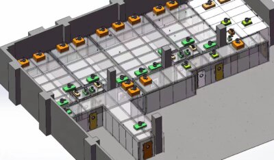
Once the inventory exists, each load needs a route plotted from its origin through to its eventual return or disposal, with every stage marked explicitly rather than assumed. A route that only shows the boundary crossing and omits staging or treatment hides the points where a load’s state is most likely to be misjudged.
Staging areas deserve particular attention because they are often shared across load types that were inventoried separately. A holding area used for incoming supplies might also serve as a temporary stop for returning reusable tools, even though the two loads carry different cleanliness states and different risk profiles. Plotting the route for each load type independently, then checking where the routes physically overlap, is how a shared staging area becomes visible as a planning issue rather than staying hidden inside a floor plan that was never cross-checked load by load.
The treatment point — where decontamination, disinfection, closed docking, or protected transfer is expected to occur — has to be placed on the route at the exact stage it happens, not assumed to occur “at the boundary” in general. Some treatment occurs before staging, some occurs at the crossing itself, and some occurs after the load has already reached its destination side. The selected control at that point must match both the hazard the load carries and the material’s compatibility with the treatment method; a load that cannot tolerate a given decontamination method needs an alternative route or an alternative point in the sequence, not a forced fit.
The destination and return legs complete the route. A route that is mapped only up to the point of use misses the outbound path, where a used or contaminated load may need a different crossing, a different treatment point, or a different staging area than the one it arrived through. Mapping both legs keeps the asymmetry between incoming and outgoing material visible, which matters because the two directions frequently carry different hazard or cleanliness assumptions even when they share a physical door.
Layer incoming supplies, samples, reusable tools, and waste separately
A single combined flow diagram tends to obscure more than it reveals, because people, clean supplies, samples, reusable tools, and waste each carry different risk logic and different handling expectations even when they move through the same physical space. Drawing them as separate layers over the same floor plan, rather than as one merged diagram, is what makes conflicts visible.
The value of separation shows up most clearly at shared infrastructure. A door, corridor, or holding area that looks adequate when only one load type is drawn through it can reveal a scheduling or control conflict once a second layer is added — for instance, if the same hold point is used for both incoming clean supplies and outgoing waste, with only a cleaning or sequencing step assumed to separate them in time. That assumption is a project decision, not a fact established by the physical layout, and it should be stated explicitly rather than left implicit in a single merged diagram.
People movement deserves its own layer for the same reason. Personnel routes interact with material routes at doors, interlocks, and staging areas, and a flow that works for material alone can still create a conflict once personnel transit is overlaid, particularly where gowning or degowning sequences intersect with a material crossing point.
Reusable tools are a layer that is frequently underdeveloped because they look, at a glance, like ordinary supplies on the way in and ordinary waste on the way out. In fact they carry a cycle: clean state in, contaminated or used state out, and then either a treatment step or a return route back to clean state for reuse. Where that cycle is not drawn as its own layer, the tool’s state at any given point on the shared floor plan is ambiguous, and ambiguity at a shared door is exactly where a control gap is most likely to go unnoticed until an exception occurs.
Mark door states, interlocks, pressure interfaces, and hold points
| Boundary map element | Show on the map | Interpretation limit |
|---|---|---|
| Door states | The door state at each mapped crossing | A door-state mark identifies the condition to review; it does not by itself establish that the boundary control is adequate |
| Interlocks | Each interface where an interlock is expected | EU GMP Annex 1 supports interlocked Grade A/B airlocks or pass-through hatches in sterile-manufacturing contexts; it is not a universal biosafety door-control rule |
| Pressure interfaces | Each pressure interface crossed by a material route | The map identifies the crossing; site-specific risk assessment still determines the required control |
| Hold points | Every place where a load is held before release or after a failed transfer | The hold must connect to the named role responsible for the next decision |
With the layered routes in place, the next task is marking the physical and procedural elements that enforce separation at each crossing: door states, interlocks, pressure interfaces, and hold points. Each of these answers a different question, and treating them interchangeably weakens the map’s usefulness.
A door state — open, closed, locked, or interlocked against a paired door — describes the condition at one instant of one crossing. Marking it on the map identifies what needs to be reviewed at that point, but the mark itself does not establish that the control is adequate for the hazard or the cleanliness requirement at that crossing; that determination depends on a site-specific risk assessment, consistent with the WHO Laboratory Biosafety Manual‘s position that risk assessment should inform proportionate biosafety controls.
Interlocks raise a related but distinct question: where is a paired-door or sequenced-access control expected, and what does it enforce in each direction? EU GMP Annex 1 supports interlocked Grade A/B airlocks and pass-through hatches, but that support applies within a sterile-manufacturing context; it does not establish a universal rule for biosafety door control, and a biosafety crossing needs its own basis for whether an interlock is required and what it is interlocking against.
Pressure interfaces are a third, separate element. A material route can cross a pressure boundary without crossing a door at all, if airflow direction rather than a physical barrier is doing the separating work. Marking every pressure interface a route crosses — not only the ones that coincide with a visible door — keeps the map from missing a control point that has no physical door to draw attention to it.
Hold points close the picture. Every place where a load is held, whether waiting for release under normal conditions or stopped after a failed transfer, needs to appear on the map, because an unmarked hold point is a place where a load’s state becomes uncertain and no one has been told to resolve it.
Assign normal release and failed-transfer decisions to named roles
| Decision branch | Named-role assignment | Route outcome to show |
|---|---|---|
| Normal release | Role that owns the release decision | Continue the load along the mapped normal route |
| Hold | Role that owns the hold decision | Keep the hold point and the next decision branch explicit |
| Failed transfer or failed cycle | Role that owns the failed-transfer decision | Show the exception route instead of allowing the normal route to continue by default |
A material flow map that shows routes and controls but no decision ownership leaves open the question of who actually authorizes a load to move, hold, or divert. Every release point, hold point, and failure branch needs a named role attached to it, not a generic reference to “operations” or “QA” as an undifferentiated group.
Normal release is the most straightforward case: a role authorizes the load to continue along its mapped route once the expected condition — treatment completed, documentation matched, state confirmed — has been met. This is where the map earns its value during routine operation, because the release role can check the map against the actual load in front of them rather than relying on memory of how the process is “supposed to” work.
Hold points require a role too, and that role is often different from the release role. A load placed on hold needs someone responsible for deciding what happens next, whether that is clearing the hold once a condition is satisfied or escalating it. Where a hold point has no assigned role, the load effectively stops being anyone’s responsibility, which defeats the purpose of having marked it as a controlled point in the first place.
The failed-transfer or failed-cycle branch is the one most often left unassigned, because it represents the exception rather than the routine path. A failed decontamination cycle, a rejected pass, or a damaged load needs its own named role and its own explicit route — one that diverts the load away from the normal path rather than defaulting it forward. An unassigned exception route is a structural gap: the map may look complete under normal conditions and still fail the moment a transfer does not go as expected, because nothing in the design tells anyone what to do or who decides. Where the facility separates aseptic and biosafety objectives across the same route, the failed-transfer role may need to differ by direction, since a failure on the way into a clean area carries different consequences than a failure on the way out of a containment area — the first risks product, the second risks exposure, and the appropriate corrective action differs accordingly.
Test the map against peak loads, cleaning, and emergency recovery
A material flow map validated only against routine, single-load conditions has not been tested against the conditions most likely to expose a gap. Peak load, cleaning, and emergency recovery each stress the map differently, and each deserves a separate pass rather than a single combined check.
Peak load testing asks whether the map still holds when multiple loads move through shared staging areas or shared crossings at the same time, rather than one at a time in sequence. A hold point sized or scheduled for a single load can become a bottleneck or, worse, a point where two load types that were meant to stay separated end up co-located, if the map was only ever walked through with one load in mind.
Cleaning introduces its own complication because cleaning activity is itself a material and personnel flow that was not necessarily included in the original inventory. Cleaning staff, cleaning equipment, and cleaning waste move through the same doors, staging areas, and sometimes the same crossings as the loads the map was built around. Where cleaning routes were not drawn as their own layer and tested against the existing controls, a cleaning cycle can inadvertently cross a boundary that the rest of the map treats as controlled.
Emergency recovery is the condition under which named-role decisions matter most, because recovery after an incident often requires departing from the normal route entirely — reversing a crossing that is normally one-directional, holding a load that would normally proceed, or routing material through a path that exists only for recovery purposes. Testing the map against an emergency scenario checks whether the hold points, named roles, and failed-transfer branches established earlier actually function when the normal sequence breaks down, rather than assuming they transfer automatically from routine operation into recovery conditions.
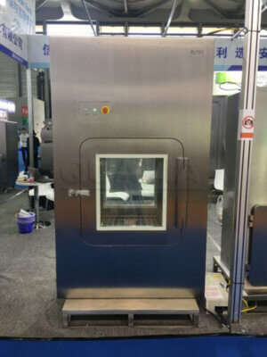
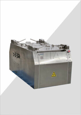
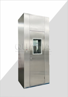
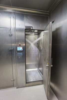
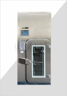
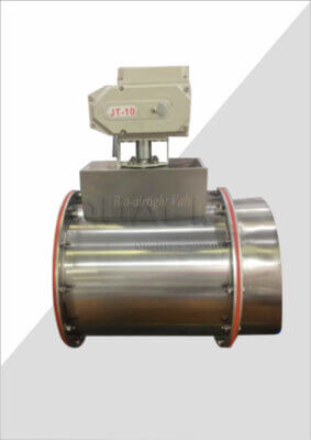
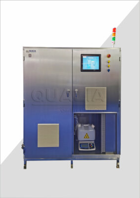
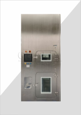
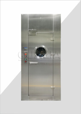
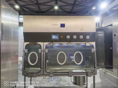
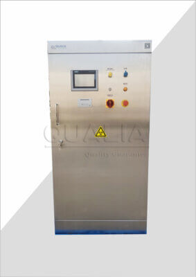
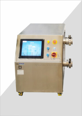
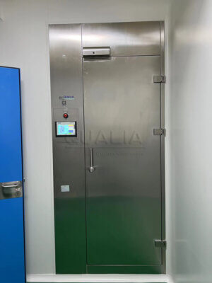
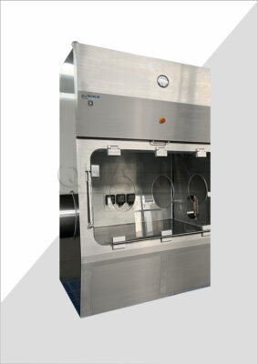
Where the completed map identifies specific crossings that need a defined transfer device — a pass box, a dunk tank, or a VHP-based transfer point, among others — that device selection becomes a separate project conversation. The map itself establishes what each crossing needs to achieve functionally; confirming which equipment satisfies that function, and how it interfaces with the rest of the facility, is the next step once the mapped requirements are in hand.
Frequently Asked Questions
Q: What information should be prepared for each load before mapping begins?
A: Record its origin, staging points, boundary crossings, destination, and return or disposal route. Also note every change in packaging or cleanliness state, where a transfer treatment or protected transfer is expected, and who owns release, hold, and failure decisions.
Q: Can the same boundary-control approach be used for both biosafety and aseptic transfers?
A: Do not assume that one approach fits both. Select and review the control against the specific hazard, material compatibility, process context, and site risk assessment; sterile-manufacturing guidance on interlocked airlocks or pass-through hatches should not be treated as a universal biosafety rule.
Q: How should a shared door or holding area be handled on the flow map?
A: Keep supplies, samples, reusable tools, and waste on separate route layers, then mark the shared point on every affected layer. Review its door state, boundary interface, hold conditions, and behavior during peak loads and cleaning so the shared location does not hide a route conflict.
Q: What should the map show when a transfer or treatment cycle fails?
A: Show an explicit hold and exception route rather than allowing the load to continue on the normal path. Name the role responsible for the next decision and keep the resulting return, recovery, or disposal branch visible for project-specific confirmation.
Q: When is a material-flow map ready for equipment-layout review?
A: It is ready for review when every load has a complete route from receipt through use, return, or disposal; state changes and boundary elements are visible; and release, hold, and failure decisions have named owners. The map should also be tested against peak loads, cleaning, and emergency recovery, while recognizing that mapping a control does not by itself prove the control is adequate.