A damper rated “gas-tight” and a damper rated “low-leakage” can look identical on a general arrangement drawing and behave very differently under a containment integrity test. The specification question is not which label sounds stronger, but which leakage duty the damper’s position in the system actually requires, and what evidence will be accepted to prove it was met.
Leakage duty behind each containment scenario
| Project scenario | Closure-duty implication | Specification boundary |
|---|---|---|
| The damper forms part of a fumigatable or sectional isolation boundary | A tighter closure is most relevant | Define the permitted leakage, test pressure, operating condition, and evidence format in the URS |
| The damper provides routine airflow control | A different leakage duty may be appropriate | Set the duty from the site-specific risk assessment and applicable national rules |
The leakage duty assigned to a damper follows from its role in the boundary, not from a generic preference for tighter hardware. Where a damper sits inside a fumigatable enclosure or forms part of a sectional isolation boundary that must hold a defined integrity during decontamination or during an isolation event, the closure is doing boundary work: it has to maintain a stated leakage performance under a stated test pressure, independent of whether air happens to be flowing through it at that moment. That is a different duty than a damper whose job is to open and close as part of normal airflow control, modulating supply or exhaust volumes without ever being asked to hold a boundary seal on its own.
The condition that changes the judgment is whether the damper is ever relied upon, on its own, as the thing standing between two zones with different hazard or cleanliness status. If another barrier already provides that separation and the damper only trims flow within a single zone, a tighter closure duty adds cost and service burden without a corresponding boundary function. If the damper is the boundary, or one of a small number of elements forming it, then its leakage performance has to be defined with the same rigor as the rest of the enclosure.
This is why the relevant question is never “is this damper gas-tight” in isolation. The applicable duty comes from a site-specific risk assessment and the national rules that apply to the facility, consistent with the proportionate approach to biosafety control measures described in the WHO Laboratory Biosafety Manual, 4th Edition. That manual is explicit that risk assessment should inform the control measure, and it is offered as summary-level support rather than as a source of fixed damper thresholds, so the output of that assessment, not a generic class label, is what belongs in the specification. The practical implication is that the URS should state the permitted leakage, the test pressure, the operating condition during test, and the format in which evidence will be supplied, rather than asking for “a gas-tight damper” and trusting the term to carry that information.
Gas-tight and low-leakage performance evidence
| Evidence element | What the evidence must state | Comparison value |
|---|---|---|
| Permitted leakage | The leakage limit applied to the closure | Provides the stated basis for judging the result |
| Test pressure | The pressure used for the leakage test | Shows whether results were produced under the same pressure condition |
| Operating condition | The damper condition represented during testing | Defines the condition to which the result applies |
| Evidence format | The form in which the result will be supplied | Shows how the leakage claim will be documented |
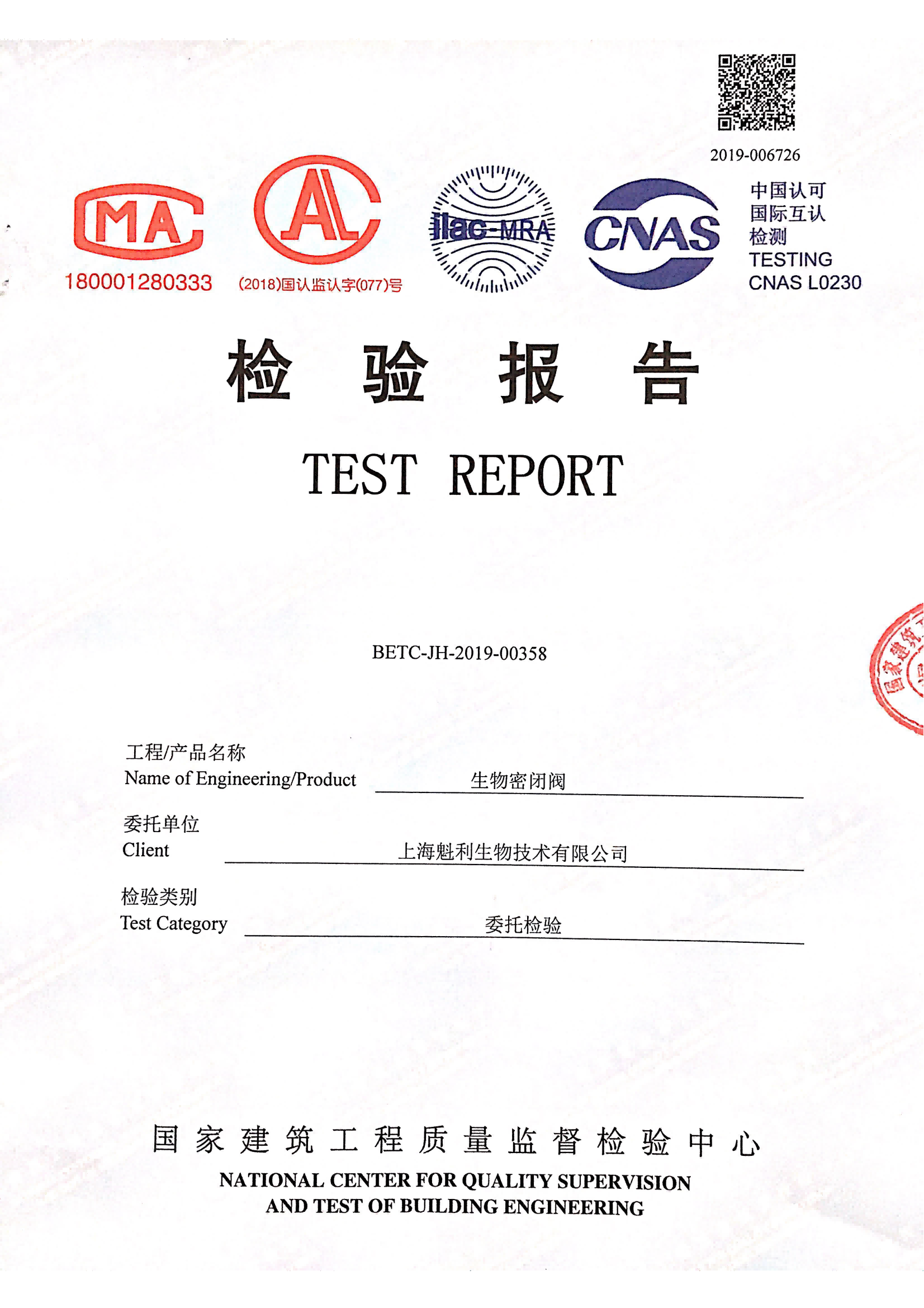
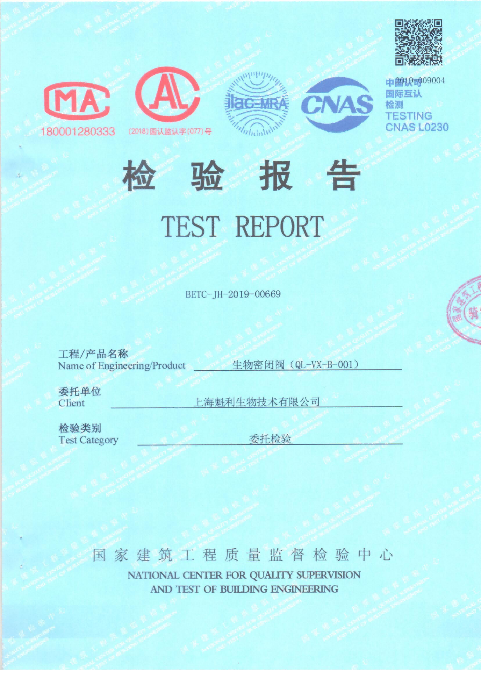
Once the duty is defined, the harder problem is comparing two suppliers’ leakage claims on the same terms. “Gas-tight” and “low-leakage” are not standardized performance figures; they are commercial descriptions that can sit on top of very different underlying test conditions. Two dampers can both be described as gas-tight while being tested at different pressures, in different physical states, and reported in different document formats, which makes a side-by-side number comparison misleading unless the underlying conditions are pinned down first.
ISO 10648-2 is relevant here because it classifies containment enclosures by leak-tightness and identifies the stages at which tightness is checked, including factory, acceptance, pre-commissioning, and periodic testing. That framework is useful for recognizing that leak-tightness is not a single one-time number but a property verified at defined stages of the equipment’s life, and that the evidence a supplier can produce at the factory stage is not interchangeable with evidence produced after installation or after a period in service. The standard’s enclosure-level scope means it does not, on its own, set a damper-specific acceptance threshold, so a supplier’s reference to ISO 10648-2 tells the buyer the test methodology lineage, not an automatic pass/fail number for the component.
For the buyer, this means the evaluation task is to confirm that competing bids state the permitted leakage against the same test pressure, describe the same operating condition during the test (for example whether the blade is held closed under the same actuator force the project will use in service), and commit to supplying evidence in a format the project’s validation and QA functions can actually use for acceptance and later re-verification. Where one supplier’s figure is quoted at a different pressure or in a different physical state than another’s, the two numbers are not comparable until they are normalized, and the project should ask each supplier to re-express the result under the project’s own test condition before treating either figure as decisive.
Seal, casing, and actuator design differences
The leakage performance stamped on a datasheet is the output of a closure system, not of any single part, and judging a damper by its blade seal alone misses how the casing and the actuator interact with that seal under real operating force. The blade seal determines the contact line where air is stopped, but the casing joints determine whether the enclosure around that blade is itself free of secondary leakage paths that would undermine a tight blade seal. A damper can carry an excellent seal material and still fail an enclosure-level test if the casing was not fabricated or installed to a comparable tightness standard, because the tested boundary includes both.
The actuator’s role is less obvious but equally consequential: the force an actuator applies to hold the blade closed, and how consistently it applies that force over repeated cycles, affects whether the rated leakage figure is still representative after the damper has been operated many times rather than tested once as new. A duty that depends on the damper repeatedly cycling into a closed, sealing position places different demands on actuator force and on seal material fatigue than a duty where the damper is normally open and only closes for an isolation event. Where the project’s operating pattern involves frequent cycling, actuator consistency and seal durability become part of the leakage question, not a separate mechanical question.
Test access is the design feature that connects the physical closure system to the ability to verify it later. A damper that cannot be reached, or whose test ports are not positioned to allow a leak test to be performed without disturbing the installed boundary, turns a theoretically tight design into one that is difficult to prove tight in service. For this reason, blade seal material, casing joint construction, actuator force and cycling behavior, and the provision of test access should be evaluated together as one closure system rather than compared line by line against a competing product’s separate datasheet figures for each part.
Decontamination compatibility and periodic retest burden
| Check | Evidence or project condition | Decision effect |
|---|---|---|
| Seal chemical resistance | Compatibility evidence for the intended decontamination duty | Shows whether the seal evidence covers the intended fumigatable boundary |
| Local leak location | The method used to locate a leak | Determines whether a detected leak can be localized for repair |
| Final tightness test | The final test result and its stated conditions | Documents final boundary tightness under those conditions |
| Retest after repair | A new test result after a repair | Rechecks tightness after the closure system has been repaired |
| Periodic testing | The project-defined test frequency and required test access | Adds recurring test work to the life-cycle comparison |
| Seal replacement | The project-specific replacement expectation | Adds service effort even when purchase prices are similar |
A leakage figure obtained on a new, unexposed damper does not by itself confirm that the same closure will perform after repeated exposure to a decontamination agent, or that a leak, if one develops, can be found and corrected without replacing the unit. The Swiss Expert Committee for Biosafety’s recommendation on structural and technical safety measures in BSL-3 laboratories flags that fumigatable-boundary penetrations need attention to seal chemical resistance, to the ability to locate a leak locally once the boundary is in service, to a final tightness test, and to retesting after any repair. That guidance is nonbinding and does not transfer a specific acceptance threshold or material proof to any other project, but the sequence of concerns it identifies is a useful checklist for what a damper’s documentation should address when it sits on a fumigatable or sectional isolation boundary.
Seal chemical resistance matters because a seal material selected for mechanical sealing performance is not automatically compatible with the specific decontamination chemistry the facility will use; where the project’s agent differs from what the seal was validated against, the leakage figure may not hold up over repeated decontamination cycles even if it was accurate when new. The ability to locate a leak locally, rather than only detecting that the boundary as a whole has failed its test, determines whether a problem can be isolated and corrected at the damper or requires disturbing a wider section of the system to find it.
The retest-after-repair step is where life-cycle effort diverges most from purchase price. A damper design that allows a clean, contained repair and a straightforward retest adds a bounded, known task to the maintenance program. A design where repair or seal replacement requires extended access work, or where retest cannot be performed without re-opening adjacent boundary elements, adds recurring effort that a one-time price comparison will not reveal. Periodic testing frequency and the test access a design permits should be treated as life-cycle variables alongside seal replacement expectations, because two bids with similar purchase prices can carry materially different ongoing service and verification effort once decontamination compatibility and retest logistics are counted.
Specification trigger that justifies the tighter option
The trigger is structural, not aesthetic: a tighter closure duty is justified when the damper is relied upon, alone or as part of a small defined set of components, to hold a fumigatable or sectional isolation boundary during the events that boundary is meant to contain. Where a damper’s function is confined to routine airflow modulation within a single zone, and no isolation or fumigation event depends on that damper holding a sealed state, a different leakage duty can be appropriate, and specifying the tightest available option in that position adds service and retest burden without a matching containment requirement.
The decision is not binary in practice, because a single HVAC system may contain dampers performing both roles, and treating all of them identically either overspecifies the airflow-control units or, more seriously, risks underspecifying a damper that is actually part of the isolation boundary but was procured as a routine control component. The project’s risk assessment is what assigns each damper to its role; the specification should then carry that assignment through as the stated permitted leakage, test pressure, operating condition, and evidence format for that specific damper, rather than applying one leakage label across the whole system.
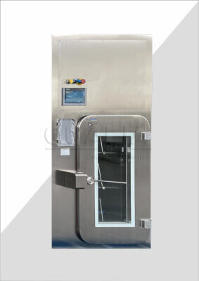
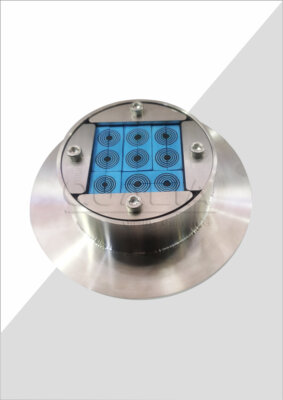
For a component identified as boundary-critical, QUALIA’s Bio-safety Isolation Damper is positioned for that fumigatable or sectional isolation duty, with configuration confirmed against the project’s own URS, test conditions, and decontamination compatibility requirements rather than assumed from a general product category. Where the project team has already completed the risk assessment and can state the permitted leakage, test pressure, operating condition, and required evidence format for a given boundary location, that information is what allows a supplier’s quotation and configuration review to address the actual duty rather than a generic gas-tight or low-leakage label.
Frequently Asked Questions
Q: Is a “gas-tight” label enough to compare two containment dampers?
A: No. Compare the permitted leakage, test pressure, operating condition, and evidence format on the same basis, and state those terms in the user requirement specification (URS) before evaluating bids.
Q: When does a project have a stronger reason to specify the tighter closure option?
A: The case is stronger when the damper forms part of a fumigatable or sectional isolation boundary. For routine airflow control, set the leakage duty from the site-specific risk assessment and applicable national rules rather than assuming the tighter option is automatically required.
Q: What project information should be prepared before requesting proposals?
A: Define the damper’s boundary role, intended decontamination duty, permitted leakage, test pressure, operating condition, required evidence format, test access, and periodic test expectation. These details let bidders respond to the same duty and make their offers easier to compare.
Q: Why should the blade seals, casing joints, and actuator be reviewed together?
A: They work as one closure system, so comparing one component alone does not establish how the complete damper will close under the specified test condition. Review the evidence for the assembled system and confirm that the actuator force, sealing interfaces, and test conditions correspond.
Q: How should life-cycle effort influence the purchase decision?
A: Compare the required test access and frequency, the project-specific seal replacement expectation, the method for locating leaks, and the need to retest after repair. These recurring tasks can distinguish two offers even when their purchase prices are similar.