

BSL-3/4 Integration Scope: What Owners Must Define Before Design
A BSL-3/4 project does not fail at commissioning because equipment underperforms; it stalls earlier, when design proceeds on an integration scope that was never fully closed. Owners who assume the BSL designation itself defines what the facility and equipment must do often discover, late in design or at integrated testing, that a pressure boundary, a transfer route, or a control interface was never assigned to anyone. Defining the integration scope before design freeze is a distinct decision from selecting equipment, and it belongs to the owner and the project team before any supplier proposal can be properly evaluated.
Scope Starts With the Intended Work and Risk Assessment
| Scope-setting input | Contribution to the integration scope | Decision boundary |
|---|---|---|
| Intended laboratory work | Identifies the work that the integrated design must support | It must be considered with the risk assessment rather than treated as a complete requirement set on its own |
| Site-specific risk assessment | Informs proportionate biosafety controls and the resulting integration scope | A summary authority reference is not a substitute for the project risk assessment or applicable national rules |
| BSL designation | Provides the containment context for defining project requirements | The designation alone does not supply every facility, equipment, interface, or evidence requirement |
The starting point for an integration scope is not the containment level label but the work the laboratory is meant to support. A BSL-3 or BSL-4 designation describes a containment category; it does not describe the specific pathogens handled, the procedures performed, the volumes processed, or the equipment that must interface with the room to support that work safely. Two laboratories at the same designation can require materially different integration scopes because the intended work differs, and treating the designation as a complete requirement set skips the step that actually determines what needs to be built.
This is why the risk assessment functions as an input to scope-setting rather than a downstream compliance exercise. The WHO Laboratory Biosafety Manual, 4th Edition, frames risk assessment as the basis for proportionate biosafety controls, which means the assessment output — not the containment label alone — should drive decisions about pressure cascades, transfer equipment, decontamination interfaces, and monitoring points. Where the risk assessment identifies specific transfer, waste, or exposure pathways tied to the intended work, those pathways become scope items that the design must address explicitly, rather than being assumed to follow automatically from a BSL-3 or BSL-4 classification.
The practical consequence for an owner is sequencing. If the intended laboratory work and its risk assessment are not finalized, or are finalized at a level of detail too general to identify specific pathways and interfaces, any integration scope drafted from the BSL label alone will carry gaps that surface later as unplanned design changes. Conversely, where the risk assessment is specific about procedures, agents, and failure modes, the owner can use it to test whether a proposed integration scope is actually complete, rather than relying on the containment category as a proxy for completeness. A WHO-level reference provides summary support for this logic but does not substitute for the site-specific risk assessment or for applicable national biosafety rules, which remain the authority an owner must apply directly.
Containment Boundaries Must Be Drawn Across Rooms and Equipment
Containment is not a property of a single room; it is a continuous boundary that has to be traced through every room, corridor, and piece of equipment that touches the controlled space. Pressure cascades, personnel and material transfer routes, exhaust paths, liquid-waste paths, and control interfaces each cross physical and equipment boundaries, and each crossing point is a place where the boundary can be left undefined if no one maps it deliberately.
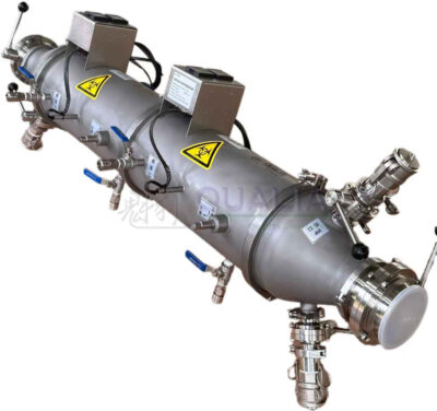
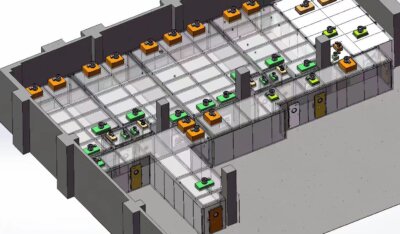
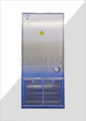
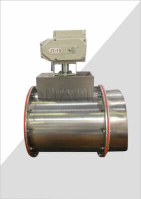
The mapping exercise matters because containment behaves differently depending on where a boundary is drawn relative to equipment versus relative to room envelopes. A pressure boundary drawn only at the room level, for instance, may not account for the pressure relationships required across a BSL-3/BSL-4 module laboratory‘s internal transitions, or across equipment such as isolation dampers that sit on the exhaust or ductwork path and are meant to preserve directional airflow under both normal and failure conditions. Where the boundary is drawn only at the architectural level, equipment-level control points risk being treated as someone else’s problem; where it is drawn only at the equipment level, the room envelope’s contribution to the same boundary risks being assumed rather than verified.
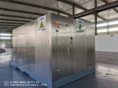
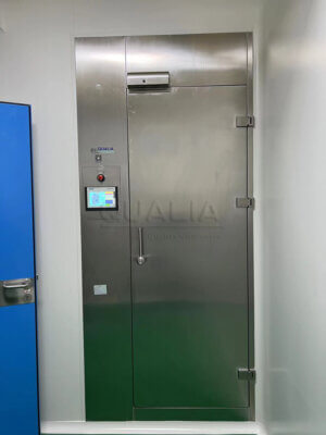
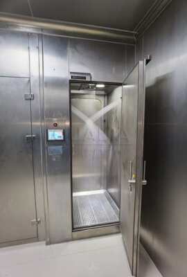
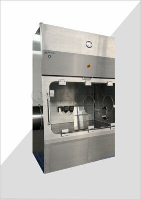
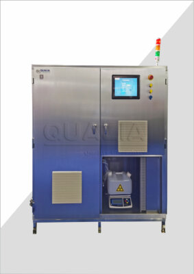
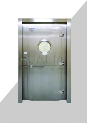
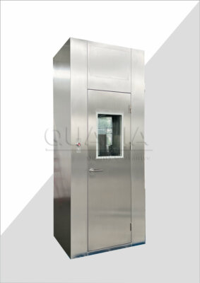
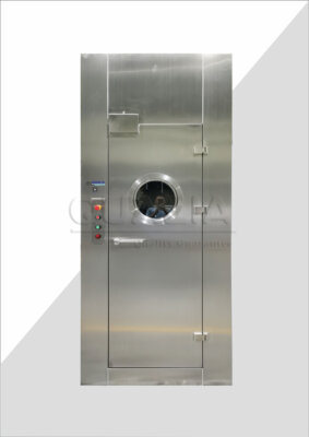
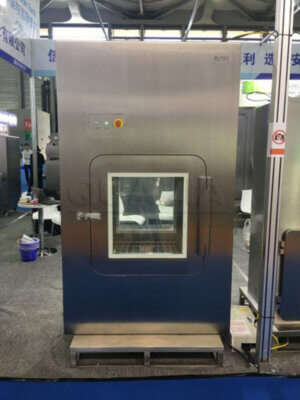
The same logic applies to transfer routes and waste paths. A transfer route through an airlock, a VHP transfer interface, or a liquid-waste path into an effluent decontamination system is only as closed as its weakest connection point, and that connection point is frequently where facility scope and equipment scope meet. The CDC/NIH Biosafety in Microbiological and Biomedical Laboratories (BMBL), 6th Edition, distinguishes BSL-3 access and airflow controls from BSL-4 suit-facility ventilation, entry, and decontamination arrangements, which is a reminder that the containment boundary’s required behavior changes with containment level and facility type — and that a boundary mapped correctly for one configuration does not transfer unchanged to another. BMBL is advisory guidance to be applied through the project’s own risk assessment and local regulatory requirements rather than as a universal pressure setpoint.
For the owner, the decision is whether every pressure boundary, transfer route, exhaust path, liquid-waste path, and control interface has been drawn across both rooms and equipment, with no segment left implicit. An unmapped segment is not a minor omission; it is a boundary with no defined behavior, which design cannot close until someone defines it.
Utilities and Controls Need Named Interface Owners
Mapping a boundary identifies where it exists; it does not establish who is responsible for its design, construction, or verification. Every interface point — a utility connection, a control signal, a monitoring point, an alarm condition — needs a named owner before it can be treated as closed, because an interface without an owner tends to be assumed complete by one party and assumed pending by another.
This matters most where control systems cross from facility-level building management into equipment-level control, or where a utility such as power, compressed air, or a decontamination medium supply crosses from facility infrastructure into a specific piece of equipment. If no one owns the interface, the specification on one side of the boundary can be written without reference to the actual requirement on the other side — a control setpoint defined by the building system without knowledge of the equipment’s actual response characteristics, or a utility sized by the facility design without confirmation of the equipment’s actual demand under failure conditions. The risk is not that the interface is wrong; it is that no one can say whether it is right, because no single party was accountable for reconciling both sides.
Naming an owner changes the nature of the open item from a shared assumption to a tracked responsibility. Where the owner is the facility design team, the equipment supplier’s role is to provide interface data early enough for the facility design to use it. Where the owner is the equipment supplier, the facility team’s role is to confirm the utility or control condition the equipment depends on. Either arrangement can work; what does not work is leaving the ownership question unresolved while both sides proceed on their own assumptions about the other.
The owner’s task at this stage is not to resolve every interface personally but to confirm that each mapped interface has exactly one named party responsible for closing it, and that the information each party needs from the other has been identified as a specific document or data exchange rather than left to informal coordination.
Supplier Deliverables Should Be Split From Facility Responsibilities
| Responsibility area | Scope to define before design | Interface evidence to identify |
|---|---|---|
| Facility utilities | Which utilities remain in the facility scope and where they interface with equipment | The utility documents and interface data the facility party must provide, plus the data the supplier must return |
| Building works | Which building works remain outside the equipment-supplier deliverables | The recorded boundary, exclusions, and documents that affect equipment integration |
| Equipment-supplier deliverables | Which accepted equipment deliverables are included in the supplier package | The supplier documents and interface data required for design review, integrated testing, and handover |
Once interfaces are mapped and owned, the next decision is which party delivers what. This is a different question from ownership: an interface owner decides the interface’s design intent, while the responsibility split decides who builds, supplies, and documents each side of it. Facility utilities, building works, and equipment-supplier deliverables are three distinct scope categories, and a project that has not separated them clearly risks a proposal review where the supplier and the owner are each assuming the other covers a given item.
Facility utilities — power, water, compressed gases, building-level exhaust, and similar services — typically remain the facility’s responsibility up to a defined connection point, with the equipment supplier’s deliverable beginning at that point. Building works, including structural, architectural, and general construction elements, usually sit outside an equipment supplier’s deliverable entirely, even where that construction directly affects how equipment integrates into the space. Equipment-supplier deliverables, once accepted into the project’s defined package, carry their own documentation and interface data requirements that the facility side needs in order to complete its own design around them.
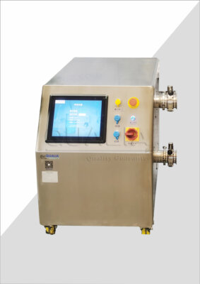
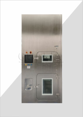
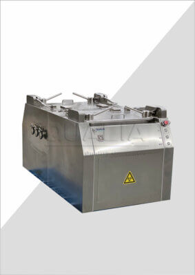
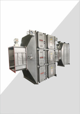
The reason this split needs to be explicit rather than assumed is that gaps and overlaps both carry cost in coordination time, and either can leave a requirement effectively unowned. If a boundary is unclear, a utility or interface item can sit in a space where each side has assumed the other is responsible for it, surfacing only when the item is needed and unavailable. Where the responsibility split is written down early, this is testable before it becomes a site problem. This is the kind of project-specific scope information that enters a supplier’s configuration or quotation review: the clearer the boundary and the interface data the owner provides, the more precisely a supplier can confirm what falls inside a proposed equipment package — for example, where a BSL-3/BSL-4 module laboratory, an isolation damper on the exhaust path, or an effluent decontamination system sits relative to the facility’s utilities and building works.
What the owner needs to confirm before design proceeds is not just the split itself but the documents and interface data each party must exchange across it — the utility specification the facility must hand to the supplier, and the interface data the supplier must return so the facility design can close around it.
Evidence Requirements Must Trace Into Testing and Handover
| Project stage | Traceability record | Decision it supports |
|---|---|---|
| Accepted requirement | The accepted requirement, its scope boundary, and its named owner | Whether the project has a defined item to carry into design review |
| Design review | Design evidence linked to the accepted requirement, including relevant interfaces and exclusions | Whether an omission is visible before site work |
| Integrated testing | Test evidence linked to the accepted requirement and the integrated scope | Whether the agreed requirement was addressed in integrated testing |
| Handover | Handover evidence linked to the requirement and its test record | Whether the final package preserves the requirement-to-evidence trail |
An accepted requirement that cannot be traced through design, testing, and handover is at risk of being lost without anyone deciding to drop it. Scope definition is not complete once a requirement is agreed; it is complete only when that requirement remains visible, with its own evidence, at every later project stage.
The mechanism here is straightforward: each stage of a containment project produces its own documentation, and if that documentation does not reference back to the originally accepted requirement, there is no way to confirm the requirement was actually carried forward rather than quietly dropped during detailed design. A requirement accepted during scope definition needs to appear again in design review, where design evidence shows how it was addressed; again in integrated testing, where test evidence shows it was actually exercised as part of the integrated system rather than assumed to work because individual components passed their own checks; and again at handover, where the final documentation package still shows the link from original requirement to test result.
The condition that changes this from a documentation nicety to a real risk is project complexity and duration. Where a project has few interfaces and a short design-to-handover timeline, informal tracking may surface a missed requirement before it matters. Where a project involves many interfaces, several parties, and a longer timeline, a requirement without a traceable record is far easier to lose between stages, because no single document carries the full history of why it was accepted and what satisfied it. This is also where the distinction between facility-level and equipment-level testing becomes relevant: a requirement tied to an interface between a supplier’s equipment and facility systems needs evidence from integrated testing specifically, not only from the supplier’s own factory-level checks, because integrated behavior is what the requirement was actually meant to confirm.
For the owner, the decision is whether the project’s evidence trail actually supports answering, at handover, which original requirements were tested as part of the integrated system and which were not. Where that trail is incomplete, the gap is not a documentation inconvenience — it is an open question about whether the requirement was met at all.
Design Freeze Depends on Closed Interfaces and Recorded Exclusions
| Design-freeze check | Evidence to confirm | Decision if unresolved |
|---|---|---|
| Scope basis | Intended laboratory work and the project risk assessment are reflected in the accepted requirements | Keep affected requirements open |
| Containment map | Pressure boundaries, transfer routes, exhaust paths, liquid-waste paths, and control interfaces are mapped across rooms and equipment | Keep the affected boundary or path open |
| Interface ownership | Every mapped design interface has a named owner | Do not close that interface |
| Responsibility split | Facility utilities and building works are separated from equipment-supplier deliverables | Record the unresolved scope boundary |
| Information exchange | Required documents and interface data from each party are identified | Keep the affected interface open until the exchange is defined |
| Evidence chain | Accepted requirements carry into design review, integrated testing, and handover | Record the missing evidence requirement before design freeze |
| Exclusions | Project exclusions are explicitly recorded | Do not treat the affected scope as closed |
Design freeze is the point where the project commits to a specific configuration, and it should depend on the scope being closed, not on the calendar. Freezing design while interfaces remain unassigned, utilities remain unsplit from equipment deliverables, or evidence chains remain unverified does not make those gaps disappear; it moves them into construction and commissioning, where they are more expensive to resolve and harder to trace back to their origin.
The condition that determines readiness for freeze is whether every item raised in scope definition has reached a closed state, meaning it has a defined boundary, a named owner, and — where relevant — an evidence record connecting it to design and test activity. An item that is still open should remain visibly open rather than being treated as resolved by default because design work has moved past it. This includes explicit exclusions: where a particular pathway, interface, or responsibility has been deliberately placed outside the current project scope, that exclusion needs to be recorded as a decision, not left to be inferred later from the absence of any documentation about it. An undocumented exclusion is indistinguishable, after the fact, from an overlooked requirement.
Where the intended laboratory work and risk assessment are reflected in the accepted requirements, where containment boundaries are mapped across both rooms and equipment, where every mapped interface has a named owner, where facility and supplier responsibilities are separated with their interface data identified, and where the evidence chain from acceptance through testing is intact, the project has a defensible basis for freezing the design. Where any of these remains undefined, the design-freeze decision should treat that specific item as open rather than proceeding on the assumption that it will resolve itself during detailed design or construction.
This is also the stage at which equipment-related scope — such as the respective deliverables for a module laboratory, containment dampers on exhaust paths, or an effluent decontamination system — should already sit inside a defined responsibility split with its interfaces closed, so that supplier coordination at the point of detailed design or delivery is confirming an already-agreed scope rather than renegotiating it.
Frequently Asked Questions
Q: Is a BSL-3 or BSL-4 designation enough to define the integration scope?
A: No. Use the intended laboratory work and the site-specific risk assessment to turn the containment context into project requirements, then check those requirements against the applicable national rules rather than treating the BSL designation as a complete specification.
Q: What should an owner prepare so supplier proposals can be compared on the same basis?
A: Prepare a common scope package that identifies the containment boundaries and routes, separates facility and building responsibilities from supplier deliverables, names interface owners, lists required information exchanges, and records exclusions. Ask each supplier to state how its proposal addresses that same package and where any boundary remains open.
Q: How should an interface that crosses equipment and facility scope be handled?
A: Give the interface a named design owner and record what each party must provide and return. For example, the record should identify the applicable utility or control boundary, the documents and interface data needed on both sides, and the evidence required before the interface can be closed.
Q: Can the design be frozen while some integration interfaces are still unresolved?
A: Keep the affected scope open until the boundary, ownership, required information exchange, and exclusions are recorded. Freezing an unresolved interface can hide an omission until site work, when responsibility and design changes are harder to manage.
Q: How can owners prevent an accepted requirement from disappearing between design and handover?
A: Assign the requirement a scope boundary and owner, then link it to the evidence expected at design review, integrated testing, and handover. Before work advances, confirm who will produce each record and how it will be matched back to the accepted requirement.