Every cable, sensor lead, or conduit that must cross a BSL-3/4 containment boundary forces the same question: has the envelope actually been drawn on paper before anyone starts counting penetrations? Getting this sequence wrong does not surface as a design flaw until commissioning, when a route that seemed routine turns out to sit inside or outside the containment line in a way nobody confirmed early. The decision is not only where a cable passes through a wall, but what evidence will later demonstrate that the boundary still holds at that point.
Where cable and conduit routes cross the containment envelope
The containment envelope is a defined line, not an assumption about which walls “seem” critical. Before any cable or conduit route is counted as a boundary penetration, the project needs a drawing that shows exactly where that envelope runs through the facility, including where it turns corners, changes floors, or excludes adjacent support spaces. A route that physically passes through a wall but stays outside the drawn envelope is not a containment penetration at all; it belongs to a different sealing task, with different sealing expectations and different verification needs.
This distinction matters because the consequence of misclassifying a route is not symmetric. Treating an envelope crossing as if it were outside the boundary leaves an unsealed or under-specified path into the containment zone. Treating a route outside the envelope as if it required boundary-grade sealing adds cost and complexity without adding containment value. Where the project team draws the envelope late, after cable and conduit routing has already been laid out by other trades, the classification exercise becomes a retrofit: existing routes are checked against a boundary that did not exist when they were planned, and mismatches are found late, when moving a penetration is far more disruptive than specifying it correctly at the start.
The condition that changes this judgment is how early the envelope is fixed relative to services design. Where the envelope is confirmed before cable and conduit routing begins, each route can be assigned its sealing task as part of normal design coordination. Where the envelope is confirmed after routing has started, the project instead has to reconcile as-routed services against a boundary drawn later, which is a review and correction exercise rather than a design exercise. The Swiss Expert Committee for Biosafety’s recommendation on structural and technical safety measures in BSL-3 laboratories addresses cable and media penetrations in a fumigatable boundary in these terms, treating the envelope and its crossings as the starting classification question before any penetration detail is specified. That guidance is nonbinding engineering advice for BSL-3 facilities and does not establish a universal threshold or a Vacu-Pass approval; it supports the classification logic, not a specific product outcome.
| Route relative to the drawn containment envelope | Crossing count | Sealing task |
|---|---|---|
| Crosses the envelope | Count the cable or conduit crossing at the boundary | Plan the boundary penetration and its wall interface |
| Remains outside the envelope | Do not count it as a containment-boundary crossing | Treat it as a different sealing task |
Opening count and spare capacity before the wall detail is frozen
Once routes are classified against the envelope, the next decision is how many separate penetrations the wall will actually carry. Every additional opening is another boundary interface that must be sealed, tested, and maintained over the life of the facility, so there is a real incentive to consolidate cable and conduit crossings into fewer, better-planned openings rather than adding a new penetration each time a service is introduced. But consolidation only pays off if the openings that remain have enough reserved capacity for cables that have not yet been specified.
This is a trade-off, not a fixed rule. Where a project commits to a small number of openings without reserving spare capacity in them, any future cable addition — a new sensor, a new control line, a replacement service — has nowhere to go except a new, unplanned penetration through the containment wall. That new opening then has to be justified, sealed, and verified outside the original design cycle, under schedule pressure that rarely favors careful boundary work. Where a project instead reserves capacity in the openings it does specify, later additions can be routed through existing, already-qualified penetrations, and the boundary detail does not need to be reopened each time equipment or instrumentation changes.
The condition that governs this choice is how well the project can anticipate its own future service needs at the point the wall detail is frozen. A facility with a stable, well-defined process may reasonably commit to a lean penetration count, because the service mix is unlikely to expand. A facility expecting instrumentation upgrades, process changes, or phased equipment installation has a stronger reason to reserve spare capacity now, even at the cost of a larger or more complex opening, because the alternative is a containment-boundary modification later. This reconciliation — fewer openings against reserved capacity — is a decision the project team needs to make deliberately, with input from whoever will be adding services to the room after initial handover, rather than treating opening count as purely a construction-cost line item.
Vacu-Pass configuration questions for the actual service mix and wall
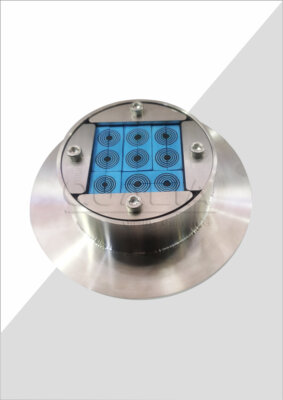
A cable and cable port penetration, such as the Vacu-Pass Cord and Cable Port, is configured to the service mix and wall construction of a specific project rather than supplied as a single fixed part. That configuration step is where the classification and capacity decisions made earlier turn into a concrete specification the supplier can quote and build against.
The service mix determines much of the detail: the number, diameter, and type of cables or conduits that must pass through the same opening, whether those services are fixed for the life of the facility or expected to change, and whether the penetration needs to accommodate a mix of cable gauges rather than a single uniform service. A port sized and sealed for one cable of a known diameter is a different specification task from a port that must seal several dissimilar cables passing through the same wall opening, and the reserved-capacity decision made earlier feeds directly into how that port is sized.
The wall itself is the other half of the specification. A penetration detail has to match the wall construction it passes through — its thickness, its finish, and how the transit interfaces with the wall’s own sealing and fumigation requirements — because the port and the wall together form the boundary, not the port alone. Where the wall construction changes partway through a project, or where the final wall assembly is not yet fixed when the port is being specified, the penetration configuration cannot be finalized either, since a mismatch between port and wall detail is exactly the kind of interface gap that later shows up as a leak path.
Because the port is one component of a larger boundary, its performance also depends on how well it interfaces with the adjoining wall construction; a correctly configured port installed against an incompatible wall detail does not deliver the boundary performance the specification assumed. The buyer’s task at this stage is to bring the confirmed service mix and the confirmed wall construction to the supplier together, since a configuration built on either alone leaves a gap that surfaces later, during inspection or use.
Local penetration checks versus applicable assembled-room testing
Verifying a cable penetration and verifying the containment performance of the room it sits in are two different evidence scopes, and neither substitutes for the other. A local check — inspecting the transit and its adjoining wall interface, including a smoke check where that method is applicable — can identify the condition of that specific seal and locate a possible leak path at that joint. It cannot, on its own, quantify how tight the assembled room is as a whole, because a room’s containment performance depends on every penetration, door, and service interface acting together, not on any single point in isolation.
Assembled-room testing addresses that whole-room question, but only within the scope that the applicable test defines for the project. A room-level test result describes the tightness of the assembled room under that test’s own defined conditions; it is not automatically evidence about the condition of any one penetration, and it does not replace the need to inspect individual transits, since a room-level result can mask a local condition that has not yet progressed to a room-level effect. The Canadian Biosafety Standard, Third Edition, addresses penetration inspection, smoke-pencil checks where applicable, and room-level pressure-decay testing within a limited, activity-specific scope, and treats these as separate verification activities rather than interchangeable ones; it is worth noting this guidance applies within its own containment-level and activity-specific framework and does not establish a universal test value. The CDC/NIH Biosafety in Microbiological and Biomedical Laboratories similarly describes sealed, cleanable BSL-3 surfaces and decontamination provisions that depend on risk, without specifying a single certification outcome that substitutes for project-specific testing.
For the project team, the practical implication is that a verification plan needs to specify both scopes explicitly, and specify them as complementary rather than as alternatives. A plan that only calls for local smoke checks at penetrations has not addressed whole-room tightness. A plan that only calls for room-level testing has not addressed whether a specific transit is sealed correctly, and will not localize a leak if the room-level result later indicates one. Where the project’s containment level or activity profile changes, the applicable room-level test and its scope may change with it, which is why this evidence plan benefits from being defined against the project’s specific requirements rather than assumed from a generic checklist; the validation documentation approach described for BSL-3 laboratory handover packages reflects this same separation between local and system-level test records.
| Evidence scope | Supported check or test | What the evidence can address | Limit to retain |
|---|---|---|---|
| Transit and adjoining wall | Inspect the penetration and wall interface; use a local smoke check where applicable | Local condition and possible leak location | A local smoke check does not quantify whole-room tightness |
| Assembled room | Use the room-level test applicable to the project | Tightness of the assembled room within that test’s defined scope | Do not infer this result from local penetration checks alone |
Cable changes, repairs and the evidence needed to re-establish the boundary
A containment boundary that has already been verified does not stay verified automatically once a cable is added, removed, or a seal is repaired. Any physical change at a penetration reopens the question of what evidence still applies and what evidence needs to be repeated to re-establish the boundary against its approved baseline.
The scope of re-verification depends on what actually changed. Where a cable is added through spare capacity that was already reserved and sealed as part of the original penetration design, the disturbance may be limited to that one transit, and the local inspection may be enough to confirm the interface is intact again. Where a seal is repaired, removed and refitted, or where a new opening is introduced because reserved capacity was not available, the disturbance is more direct, and the project needs to decide whether the local check alone is sufficient or whether the applicable room-level test also needs to be repeated, since a repair at one point does not confirm that the rest of the assembled room’s tightness is unaffected.
This is a project-specific decision, not a fixed rule, because it depends on how the original baseline was established and documented. A project that recorded its original local and room-level test results in detail has a clear reference to compare against after any change. A project without that baseline has to reconstruct what “acceptable” looked like before deciding what “still acceptable” means after a repair. This is the same logic addressed in guidance on re-verification triggers for BSL-3/4 integrated systems, where changes such as filter work, control updates, or major repairs prompt a defined review of what must be re-tested rather than an assumption that a repair automatically restores the original verified condition.
The condition that determines the extent of re-verification is the relationship between the change and the original test scope: a change confined to a single, already-qualified interface may only require repeating the local check at that interface, while a change that affects the wall’s sealing performance more broadly, or that was not anticipated in the original penetration design, is more likely to require repeating the room-level test as well. The project team’s task after any cable change or seal repair is to make that scope decision explicitly, against the approved baseline, rather than treating the repair itself as evidence that containment has been restored.
Frequently Asked Questions
Q: Do all cable and conduit routes count as containment-boundary penetrations?
A: No. Mark the containment envelope on a drawing and count the routes that actually cross it. A route outside that envelope has a different sealing task.
Q: How can we reduce wall openings without making future cable additions harder?
A: Plan fewer boundary openings together with reserved service capacity before the wall detail is frozen. Map the known crossings and the intended reserve so a later addition does not depend on an unplanned new penetration.
Q: What should a Vacu-Pass cable-port specification account for?
A: Define the actual cable service mix, the wall interface, and the capacity to reserve. Confirm which services cross the containment envelope, then specify inspection of the transit and adjoining wall as part of the project’s verification plan.
Q: Can a local smoke check replace an assembled-room test?
A: No. Where applicable, a local smoke check can help locate leakage at a penetration, but it does not quantify whole-room tightness. Inspect the transit and adjoining wall, and use the room-level test applicable to the project for assembled-room evidence.
Q: What should happen after a cable change or seal repair?
A: Compare the change with the approved baseline and decide which local penetration checks and room-level tests need repeating. The checks should address the changed boundary rather than assuming the earlier result still applies.