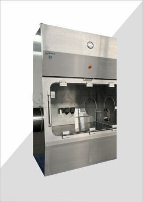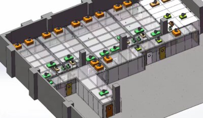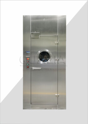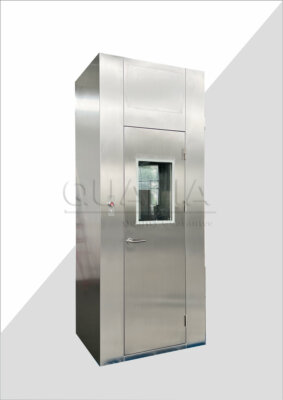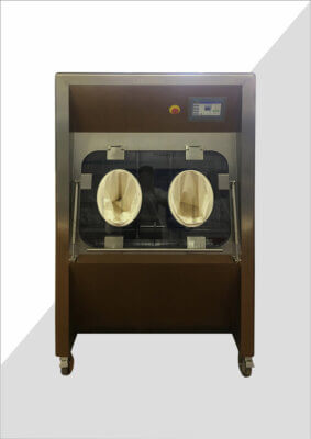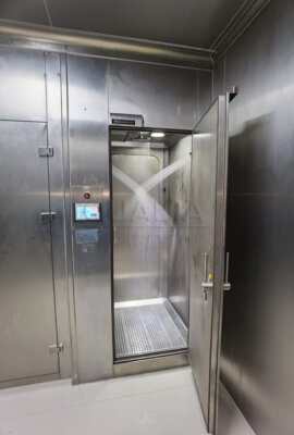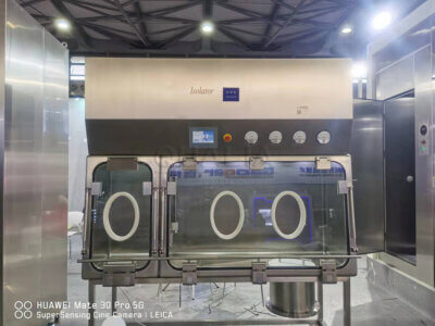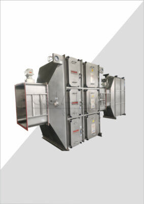

Choosing between an aseptic isolator and a sterility test isolator is not a matter of picking a bigger or smaller version of the same enclosure. The decision depends on which process the isolator protects and what that process demands from pressure control, transfer paths, and bio-decontamination evidence. Getting the scope definition wrong early tends to surface later, when chamber layout, glove placement, or transfer hardware no longer fit the actual intervention sequence.
Protection Goals That Separate Aseptic Processing From Sterility Testing
An aseptic processing isolator and a sterility test isolator both use a sealed barrier to separate a controlled interior from the surrounding room, but the process each one protects is different, and that difference should set the specification before any equipment feature is discussed. Aseptic processing isolators exist to protect a manufacturing process and the product moving through it, typically across a filling or compounding sequence where open product is exposed to the isolator interior for an extended period. Sterility test isolators exist to protect a test method, where a defined sample is introduced, manipulated, and incubated or otherwise processed without the result being compromised by contamination introduced during the test itself.
This distinction matters because the protection objective drives different design logic even when both isolators look similar from outside. Where the isolator protects a manufacturing process, the enclosure has to sustain protection across variable batch durations, multiple interventions, and a product stream that may change in format or container type across campaigns. Where the isolator protects a sterility test, the enclosure has to sustain a repeatable, verifiable condition across a shorter, more standardized sequence of sample handling steps, with the emphasis on demonstrating that the test environment did not introduce a false result.
ISO 13408-6:2021 addresses the specification, selection, qualification, bio-decontamination, validation, operation, and control of aseptic isolator systems, but its official abstract does not specify sterility-test-isolator requirements as a distinct category. That gap is a planning fact, not an oversight to work around: a buyer evaluating a sterility test isolator cannot treat an aseptic-processing standard’s framework as a complete answer for test-isolator acceptance criteria, and should expect to define sterility-test-specific requirements separately, even where the physical barrier technology overlaps.
The practical consequence for a buyer is that the isolator label on a quotation or datasheet is not sufficient to confirm fitness for either purpose. A unit built around aseptic processing logic may need rework to serve a sterility testing application, and the reverse holds as well. The scope decision has to start from what the process requires the barrier to protect, not from the category name the equipment carries in a catalog.
Process Mapping for Interventions, Materials, Waste, and Transfers
| Process-map element | Project-specific question to resolve | Decision informed |
|---|---|---|
| Interventions | Which interventions must the planned process accommodate? | Intervention scope before chamber layout is frozen |
| Materials | Which materials move through the isolator, and by which path? | Material routes and chamber layout |
| Waste | Which waste movements must be mapped? | Waste paths and chamber layout |
| Transfers | Which transfer path applies to each planned movement? | Transfer-route definition and chamber layout |
Before chamber layout is fixed, the process that will run inside the isolator has to be mapped in enough detail to know what the barrier, the glove positions, and the transfer points must accommodate. This mapping exercise is distinct from the protection-objective decision above; it is about translating that objective into the physical and procedural detail the isolator design has to support.
Interventions are the starting point. Every manual or mechanized action that must occur inside the chamber during the process, from sample or product handling to equipment adjustment, defines where glove ports, half-suits, or other access points need to sit, and how many are needed. An isolator configured for a process with few interventions can use a simpler glove arrangement than one supporting a process requiring frequent manipulation at multiple points inside the chamber, and that difference changes both chamber geometry and the ergonomics the operator will live with.
Materials entering the isolator follow a separate logic. The buyer needs to know what moves in, in what format, and by which route, because the transfer method has to match the material’s sensitivity to the bio-decontamination process and to the time it will spend in transit. A material that cannot tolerate the isolator’s planned decontamination approach needs an alternate entry path, which changes the transfer hardware the isolator requires.
Waste leaving the isolator is often treated as an afterthought, but waste movement has its own contamination-control logic, particularly where hazardous or contaminated material must exit without compromising the barrier’s integrity or cross-contaminating the transfer path used for incoming materials. Mapping waste movement separately from material movement prevents the layout from forcing both to share a route that suits neither.
Transfer paths tie these elements together. Each planned movement in or out of the chamber, whether of product, sample, waste, or ancillary material, needs a defined transfer method appropriate to that specific movement, and the isolator’s transfer chambers and ports have to be sized and positioned accordingly. Where this mapping happens before layout is frozen, the resulting chamber design reflects the real process; where it happens after, the buyer is left retrofitting a layout that was never built around these movements in the first place.
Barrier Design Choices for Pressure, Gloves, and Chamber Layout
Pressure regime, glove configuration, and chamber layout are the physical expression of the protection objective and the process map, and each carries its own set of trade-offs rather than a single correct answer.
Pressure control inside the isolator can run positive or negative relative to the surrounding room, and the choice follows from what is being protected and from what. A positive-pressure regime pushes air outward through any breach, which supports protecting the product or sample inside the chamber from contamination originating in the room. A negative-pressure regime draws air inward, which supports protecting the room and operator from material inside the chamber. An isolator cannot be optimized for both directions of protection simultaneously in the same zone, so where a project involves both a product-protection concern and a hazard-containment concern, the design needs zoned or cascaded pressure arrangements rather than a single uniform pressure decision.
Glove configuration follows directly from the intervention map. The number, placement, and size of glove ports determine what an operator can physically reach and manipulate without compromising the barrier, and this is where a layout decided too early tends to create lasting ergonomic friction. A chamber with glove ports positioned for one intervention sequence may leave an operator working at an awkward angle if the actual process requires reaching a different zone of the chamber, and that friction compounds across repeated use.
Chamber layout itself has to reconcile the intervention points, the transfer locations, and the equipment or fixtures that sit inside the chamber, all within a footprint that keeps the barrier’s integrity intact. A chamber designed around a single product or sample format offers a tighter, more purpose-built layout, while a chamber intended to serve variable formats across future campaigns needs reserved space and flexible fixturing, trading some efficiency for adaptability. The buyer’s confirmation point here is whether the isolator is being specified for a fixed process or for a process expected to change, because that answer changes how much layout flexibility is worth building in from the start.
Bio-Decontamination Planning Around Loads, Materials, and Aeration
| Evidence element | Project-specific basis to match | Applicability boundary |
|---|---|---|
| Enclosure | Actual enclosure | Evidence applies to the enclosure assessed |
| Load patterns | Actual load patterns | Evidence applies to the load patterns assessed |
| Materials | Actual materials | Evidence applies to the materials assessed |
| Aeration conditions | Actual aeration conditions | Evidence applies to the aeration conditions assessed |
Bio-decontamination cycle evidence is only meaningful in relation to the specific enclosure, load pattern, materials, and aeration conditions it was generated against. A cycle validated for one configuration does not automatically transfer to another, even within the same isolator family, because the variables that determine whether a bio-decontamination agent reaches and clears every relevant surface are specific to what is inside the chamber and how it is arranged.
Load pattern is one of the clearest variables. The way items are arranged inside the chamber, including their spacing, shielding of one item by another, and orientation relative to the distribution of the bio-decontamination agent, affects whether every surface receives adequate exposure. A load pattern used during cycle development that does not resemble the load pattern used in actual operation leaves a gap between the evidence generated and the condition the isolator will actually run.
Materials matter for a related but distinct reason: different materials interact differently with a bio-decontamination agent, in terms of absorption, surface interaction, and compatibility, and a cycle developed against one material set does not confirm performance against a different one introduced later in the process lifecycle.
Aeration conditions close the loop. After a bio-decontamination cycle, the chamber needs to clear residual agent to a condition suitable for the next step in the process, and aeration time and completeness depend on chamber geometry, load mass, and material off-gassing behavior. A chamber reconfigured after cycle development, or a load changed in composition or volume, can shift aeration behavior even where the decontamination exposure step itself is unchanged.
EU GMP Annex 1 addresses contamination-control strategy, isolator barriers, controlled bio-decontamination, transfer, and validation evidence within its EU sterile-manufacturing context, but it does not supply a universal cycle recipe applicable across all configurations, nor does it serve as occupational-containment proof. This reinforces that bio-decontamination evidence has to be read as conditional on the specific enclosure, load, material, and aeration conditions under which it was generated, and a buyer reviewing supplier-provided cycle data should confirm that those conditions match the project’s actual configuration rather than a generic reference case.
Facility Interfaces for Utilities, Controls, and Service Access
An isolator does not function as a standalone object; it draws utilities, exchanges control signals, and requires physical access for service, and each of these interfaces has to be coordinated with the facility rather than treated as internal to the equipment itself.
Utility connections, whatever form they take for a given isolator, have to be planned against the facility’s existing capacity and routing, and a mismatch between what the isolator requires and what the facility room can deliver at the planned location becomes a coordination problem rather than a simple installation step. Where a facility’s utility infrastructure was designed before the isolator was selected, the buyer and the facility engineering team need to confirm early whether the room can support the isolator’s demands without rerouting or capacity changes.
Control integration raises a parallel question: does the isolator’s control system operate independently, or does it need to exchange signals with building management or process control systems already in place? An isolator that must report status, alarms, or cycle data to a broader facility control system needs that interface defined before installation, because retrofitting control integration into an installed isolator is a materially different exercise than specifying it up front.
Service access is often underweighted relative to utilities and controls, but it determines whether the isolator can be maintained without disrupting adjacent operations or requiring extensive disassembly. An isolator installed with generous clearance around service points supports more straightforward maintenance; one installed tightly against a wall or other equipment, without that clearance considered at the layout stage, can turn routine service into a disproportionately disruptive event. This is a point where project information the customer supplies about room layout and planned equipment placement becomes directly relevant to how the isolator’s configuration is reviewed, since service access requirements have to be checked against the actual room plan rather than assumed generically.
None of these interfaces are fixed by the isolator alone; each depends on what the facility already has in place and what the project team is willing or able to change, which is why interface coordination belongs early in the planning sequence rather than at installation.
Acceptance Evidence From URS Through FAT, SAT, and Qualification
| Traceability stage | Question to answer | Evidence position |
|---|---|---|
| User requirements | Which project requirement needs acceptance evidence? | Starting point for the evidence trace |
| Factory testing | Which applicable requirements are addressed at factory testing? | Factory-stage evidence linked to user requirements |
| Site testing | Which applicable requirements are addressed at site testing? | Site-stage evidence linked to user requirements |
| Qualification | Which applicable requirements are addressed in qualification? | Qualification evidence linked to user requirements |
Acceptance evidence for an aseptic or sterility test isolator has value only if it can be traced back to a specific requirement the project defined at the outset. A user requirements specification that states what the isolator must do, under what conditions, and to what effect gives the project a baseline against which every later test result can be checked for relevance.
Factory testing is the first point where that baseline gets exercised against built equipment, but factory testing can only address requirements that are testable in the factory environment, which excludes anything dependent on the final facility’s utilities, room conditions, or integration with other installed equipment. A buyer reviewing factory test results should check which user requirements those results actually address, rather than assuming factory testing closes out the full requirement set.
Site testing picks up where factory testing leaves off, addressing requirements that depend on the isolator being installed in its intended location, connected to actual facility utilities, and operating alongside whatever else shares that space. Some requirements will only be testable at this stage, and a project plan that treats site testing as a formality rather than a distinct evidence-generation step risks discovering integration issues later than they could have been caught.
Qualification closes the trace by confirming that the installed, connected, and operating isolator performs as the user requirements specified, under conditions representative of actual use. ISO 14644-7:2004 addresses minimum design, construction, installation, test, and approval requirements for separative devices, framed around the customer-supplier requirement relationship, though its abstract scope does not extend to application-specific processes, and the edition itself is marked for revision, which means a buyer should confirm current applicability rather than relying on it as a fixed reference.
The value of this trace is that it lets the project team, and QUALIA’s project review process when a configured isolator is being evaluated, confirm that every stated requirement has a corresponding piece of evidence at the appropriate stage, rather than discovering gaps only when the equipment is already installed and running.
Frequently Asked Questions
Q: Can the same isolator concept be assumed to suit both aseptic processing and sterility testing?
A: No. Define the intended process, protection objective, and applicable GMP or compendial requirements first, then check whether the proposed isolator scope supports that specific use.
Q: What information should be prepared before an isolator URS is finalized?
A: Document the process and protection objective, planned interventions, material and waste movements, transfer paths, facility interfaces, bio-decontamination basis, and required acceptance evidence. This gives each requirement a project-specific basis before the chamber layout is fixed.
Q: How should a buyer assess proposed pressure, glove, and chamber-layout choices?
A: Check each choice against the protection objective and the mapped interventions, materials, waste, and transfers. Any choice that cannot be traced to those project needs should remain an open design question rather than an assumed requirement.
Q: Can bio-decontamination evidence from another isolator or cycle be reused for a new project?
A: Only after its applicability is established for the actual enclosure, load patterns, materials, and aeration conditions. A mismatch in any of these factors should be identified for project-specific evaluation rather than treated as covered by a universal cycle.
Q: What facility information should be resolved before equipment integration is agreed?
A: Define the project-specific utility connections, control interfaces, and service-access needs, then assign how each interface will be confirmed. Leaving these categories undefined can prevent the equipment concept from becoming a testable facility plan.
Q: How can acceptance evidence be made traceable from procurement through qualification?
A: Link every user requirement to the stage where it will be evaluated: factory testing, site testing, qualification, or another explicitly agreed step. Before approval, identify any requirement that lacks a named evidence stage.