Before setting pressure cascades, alarm logic, or enclosure specifications for an HPAPI process, a project team has to answer a more basic question: which protective function is doing the work, and what happens when that function stops? An extract fan and a sealed glovebox wall can both reduce exposure, but they fail differently, recover differently, and demand different operator responses. Getting this boundary wrong before design starts means the control strategy is built on an assumption nobody confirmed.
Classify Controls by What They Do and What They Depend On
| Control layer | Supported examples | Primary dependency | Project boundary to define |
|---|---|---|---|
| Active controls | Extract airflow, pressure control, alarms, and automated sequences | Utilities, sensors, and a defined response to loss of function | State the safe condition and how operators will recognize and manage loss of the active function |
| Passive controls | Enclosure walls, sealed interfaces, and closed transfer paths | Physical integrity and disciplined access | State how boundary integrity and access conditions will be maintained |
| Interacting layers | A passive boundary combined with an active system | Both physical integrity and the active function establishing direction or capturing leakage | Define what protection remains and what response applies when either layer is unavailable |
Every control measure in an HPAPI process falls into one of two behaviors: it acts, or it blocks. Active controls act — they move air, hold a pressure differential, trigger an alarm, or execute a programmed sequence. Passive controls block — they rely on a wall, a seal, or a closed transfer path staying physically intact. This distinction is not cosmetic. It determines what the control depends on to keep working, and therefore what can take it away.
An active control depends on something external to the barrier itself: electrical power, a working sensor, a control loop, an operator who responds to an alarm. Remove any one of those dependencies and the active function stops, even though every physical component of the system is still in place. A passive control depends on none of that. A gasket seals or it doesn’t; a wall contains or it’s breached. Its performance is a property of its condition, not of any ongoing action.
This has a direct consequence for how a project team evaluates a containment strategy. Where the control basis leans on active function — extract airflow direction, for instance, or an automated interlock — the project has to specify not just the function but the architecture that keeps it running: utility redundancy, sensor placement, how fast a loss is detected. Where the basis leans on passive function — a sealed enclosure, a closed transfer device — the project instead has to specify how integrity is verified and maintained over time, and what access discipline prevents the seal from being defeated by routine use.
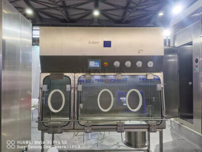
Most real HPAPI systems combine both. An isolator has passive walls and an active extract system maintaining negative pressure inside them. A closed transfer path may be entirely passive in its sealing mechanism but sit inside a process that also depends on active pressure control to manage any incidental leakage. The classification exercise is not about sorting equipment into two bins — it’s about identifying, for each protective function the project is relying on, whether its continuity is active or passive, because that answer changes what evidence and what failure planning the project needs to produce before design is finalized.
Map Active Functions Across Extraction, Pressure, Alarms, and Automation
Extract airflow, pressure control, alarms, and automated sequences look like separate systems, but they share one dependency structure: each requires a continuously available input — power, a control signal, a sensor reading — and a defined response when that input is lost. Treating them as a single category during boundary-setting avoids the trap of specifying each one in isolation and missing that they often share the same point of failure.
Extract airflow establishes a direction of movement, drawing air away from an operator-occupied space and toward a controlled discharge or filtration point. Its protective value exists only while the airflow is actually moving in that direction at a rate sufficient to overcome disturbances at an opening or a seal. Pressure control is related but distinct: it maintains a differential between zones, which determines which direction air moves across any leak path, intentional opening, or imperfect seal. Where extraction and pressure control are both active functions on the same barrier, a disturbance to one — a damper fault, a changed resistance in ductwork — can alter the other even if its own components are undamaged.
Alarms and automated sequences add a further layer: they are not protective functions in themselves but the mechanism by which a loss of protection becomes visible and actionable. An alarm that depends on the same power source or control network as the function it monitors can fail silently alongside that function, which is a condition the project needs to examine explicitly rather than assume away. Automated sequences — a programmed response to an out-of-range condition — depend on correctly sensing the condition and executing a response that has been validated for the actual failure mode encountered, not just a generic “alarm and shutdown.”
For a project team, the practical task is to map each active function to its dependency chain and ask what else goes down with it. Where a single utility or control network supports multiple active functions, a single fault can remove more protection than a review of each function individually would suggest. Where functions are supported by independent utilities or separated control loops, a fault in one leaves others intact. This mapping exercise determines whether the project’s redundancy strategy addresses the actual failure modes or only the ones that were considered function by function.
Define Passive Protection Through Enclosures, Seals, and Closed Transfers
Passive protection does not act; it persists. An enclosure wall, a gasketed door, a closed transfer device — each provides protection by maintaining a physical boundary that does not depend on power, a sensor, or a control decision to remain effective. This is their advantage: they do not fail when a utility is interrupted. It is also the source of their particular vulnerability: because nothing is actively monitoring their condition moment to moment, degradation can go unnoticed until it is tested by an actual challenge — a transfer operation, an access event, a pressure excursion from elsewhere in the system.
The protective value of a passive boundary is a function of its integrity and the discipline of access across it. A wall or window that has never been breached offers full protection; the same wall with a compromised seal, an improperly closed port, or a transfer device used outside its validated method offers something less, and that reduction is not announced by an alarm the way an active function’s failure might be. This is why passive controls are described through physical integrity and access discipline rather than through continuous performance metrics: the relevant question is not “is it working right now” but “has its condition been preserved since it was last verified.”
Closed transfer paths deserve particular attention because they combine a passive sealing principle with a procedural element: the transfer is only as closed as the method used to execute it. A device capable of maintaining containment when operated correctly offers no protection if the operating sequence is interrupted, skipped, or performed incorrectly. This means the passive hardware and the procedure governing its use have to be evaluated together, not as separate project elements — a well-designed seal does not compensate for an undefined or poorly controlled transfer method, and a disciplined method cannot compensate for hardware that has lost integrity.
For a project, this reframes what “passive” means in practical terms: it is not “no maintenance required” but “protection maintained through condition and discipline rather than through function.” The project’s obligation is to define how that condition is confirmed and how access is controlled, since neither happens automatically the way an active system’s self-monitoring might suggest it does.
Test the Interfaces Where Active and Passive Layers Rely on Each Other
The point where an active system and a passive boundary meet is where a containment strategy is actually tested, because each layer’s stated protection is often conditional on the other layer functioning as expected. A passive enclosure wall may be designed to limit release on its own, but if the project’s control basis also assumes an active extract system is establishing inward airflow direction at every opening in that wall, then the wall’s independent protective value and the system’s combined protective value are two different numbers, and the project needs to know which one it is actually relying on.
This matters most at defined openings: a transfer port, a glove sleeve interface, a door. These are points where the passive boundary is interrupted by design, and where an active function is frequently asked to compensate for that interruption — maintaining a directional airflow across the opening, for instance. Where the active function is present and working, the opening behaves as the combined system intends. Where the active function is absent — because of a utility loss, or because the opening is used in a mode the active system wasn’t configured to manage — the passive boundary at that point may offer far less protection than the enclosure does elsewhere, because the opening was never designed to be passively sufficient on its own.
The project consequence is that boundary interfaces cannot be evaluated by looking at the active system’s specification or the passive system’s specification separately. The question to resolve is: what does this interface provide when both layers are intact, and what does it provide when one is not? Where the answer to the second question is “very little,” the project has identified a point where the control basis is more fragile than the overall equipment description might suggest, and where additional procedural or design attention is warranted. Where the answer is “a reduced but still meaningful level of protection,” the project has a genuine layered defense and can plan its failure response accordingly.
Set Safe States for Utility, Sensor, Airflow, and Seal Failures
| Failure state | Control layer affected | Decision boundary | Project-specific definition required |
|---|---|---|---|
| Utility or power loss | Active | Continued operation of extract airflow, pressure control, alarms, or automated sequences cannot be assumed | Safe condition, operator recognition, and response |
| Sensor or control loss | Active | The active function and its automated or alarm response cannot be assumed | Safe condition, operator recognition, and response |
| Airflow loss | Active, with consequences at the passive boundary | Direction or leakage capture established by the active system cannot be assumed | Safe condition, remaining passive protection, operator recognition, and response |
| Seal failure | Passive, with consequences for the combined layers | Physical boundary integrity cannot be assumed | Safe condition, applicable access limits, operator recognition, and response |
Classifying controls and mapping their dependencies leads to the question a design basis has to actually answer: what is the safe condition when each dependency is lost, and how does an operator recognize that it has been lost? This is not a single answer across the system — it differs by which layer is affected and what else depends on it.
A utility or power loss removes the foundation under every active function at once: extract airflow, pressure control, alarms, and automated sequences can all be affected simultaneously if they share that utility. The project has to define what state the system defaults to, whether that default itself requires power to achieve, and how an operator becomes aware that this state now exists rather than discovering it through some other means.
A sensor or control loss is narrower but no less important: it removes not the active function necessarily, but the system’s ability to know whether that function is working and to respond automatically if it is not. A control loop can continue operating on stale or incorrect information after a sensor fault, which is a different hazard than an outright stop, and the safe-state definition has to address both possibilities separately.
An airflow loss sits across both layers: it is an active-function failure in itself, but its consequence lands on the passive boundary, because direction and leakage capture at an opening were depending on that airflow. The safe state here has to specify what passive protection remains once the active contribution is gone, not just what happens to the airflow system itself.
A seal failure is the passive case: it removes a boundary condition that was not actively monitored to begin with, so recognition depends on inspection, testing, or a downstream indication rather than an automated signal. The safe state has to define applicable access limits once integrity cannot be assumed, since the failure may not be immediately visible the way an active alarm condition is.
In each case, the project-specific work is the same: state the safe condition, state how it is recognized, and state how it is managed, rather than relying on the general description of the equipment to imply an answer.
Document Verification Evidence Against the Exposure-Control Basis
| Evidence type | Supported use | What it does not establish |
|---|---|---|
| Hazardous-substance GMP risk assessment using available occupational exposure limit information | Supports a risk-based control basis and prioritization of facility, closed-system, and barrier controls | A compound-specific exposure limit, exposure band, or universal control design |
| Occupational exposure banding | Supports risk-management decisions when an authoritative chemical-specific occupational exposure limit is unavailable | A containment-performance result from the exposure-band label alone |
| SMEPAC containment performance assessment | Supports standardized evaluation under defined conditions using airborne-emission and surface-deposition sampling | Protocol details or acceptance interpretation without the full guide and a defined scenario |
Once a project has classified its controls and defined its failure states, the remaining task is matching the right evidence to the right claim, because different evidence types answer different questions and none of them substitutes for another.
A hazardous-substance GMP risk assessment — the approach described in WHO GMP for Pharmaceutical Products Containing Hazardous Substances — supports a risk-based control basis built on available occupational exposure limit information, and it gives priority to facility, closed-system, and barrier controls over administrative measures. What it does not do is establish a compound-specific exposure limit or hand the project a ready-made control design; it frames the approach, not the number.
Where no authoritative chemical-specific exposure limit exists, occupational exposure banding — as described by NIOSH — supports the risk-management decision in that gap, assigning a band based on available hazard information so that a control strategy can proceed without waiting for a limit that may not arrive. This is a planning input, not a containment-performance result: an exposure band describes the hazard, not how well a particular enclosure, extract system, or transfer device actually performs against it.
That performance question is answered by a different evidence type: standardized containment performance assessment, such as the SMEPAC methodology referenced by ISPE, which evaluates containment under defined conditions using airborne-emission and surface-deposition sampling. This is the evidence that connects a specific piece of equipment, configured and operated in a specific way, to an actual measured outcome — but only under the scenario the assessment was run against, and only with the full protocol and its acceptance interpretation applied, not as a general label.
For a project team assembling a verification plan, the task is to line these up against the claims they are actually being asked to support: the risk assessment and exposure banding inform what control approach and priority the project adopts; the performance assessment confirms whether the chosen equipment, as configured, delivers the result the project needs under the conditions that matter for that process. When a project submits its process parameters, exposure-control basis, and equipment configuration for review — as happens when evaluating a configured system such as an OEB4/OEB5 isolator or a closed restricted access barrier system for a specific application — this is the information that determines whether the proposed configuration addresses the actual failure states and verification evidence the project has identified, rather than a generic version of the same equipment family.
Frequently Asked Questions
Q: What should be compared when choosing between an OEB4/OEB5 isolator and a closed RABS for an HPAPI project?
A: Compare the actual control layers required by the project: active functions, passive boundaries, transfer interfaces, utility and sensor dependencies, failure responses, and the planned verification scenario. A product category or exposure-band label alone does not establish project fit or containment performance.
Q: Can the same containment condition be assumed after extraction, pressure control, or airflow is lost?
A: No. An intact passive boundary may still limit release, but airflow direction or leakage capture provided by the active system cannot be assumed. Define in advance what protection remains, any access restrictions, how operators will recognize the condition, and the required safe response.
Q: How should a project proceed when no authoritative chemical-specific occupational exposure limit is available?
A: Use occupational exposure banding to support the risk-management and control-selection basis, while keeping its limitation explicit. The exposure band does not prove containment performance, so the project still needs a defined operating scenario and suitable verification evidence.
Q: What evidence is needed to verify that the selected control strategy performs as intended?
A: Match the evidence to the claim being evaluated. The risk assessment establishes the exposure-control basis, while a SMEPAC containment performance assessment can evaluate airborne emission and surface deposition under defined conditions; the protocol, scenario, and acceptance interpretation must be specified for the project.
Q: What information should be ready before the active and passive control design is reviewed?
A: Prepare the hazard or exposure-band basis, the relevant closed-transfer and access conditions, each active function and passive boundary, and the safe condition for power, sensor, airflow, or seal failure. Also define how each failed state will be recognized, managed, and linked to verification evidence.