

Before a cRABS can be integrated into an existing aseptic filling or processing line, every route by which material, tools, samples, and waste currently cross the room boundary must be documented as a named flow with a defined start point, end point, and packaging state. Without that map, the barrier design and the transfer equipment around it are priced against an incomplete picture—and the gaps surface during commissioning or qualification, not before. The fundamental task is building an item-flow register that the project team, the supplier, and quality can all work from before any equipment arrangement is fixed.
Map Material and Tool Entry Routes
Every item that crosses the barrier during a campaign leaves a trace in the process that a cRABS integration will have to account for.
Start by listing what physically enters the working zone: primary containers, stoppers, closures, fill needles, spatulas, sampling tools, in-process test kits, cleaning agents, lubrication materials, and any hand tools used during the run. Each entry is a data row, not a category. The row should carry the item’s name, its packaging state at the point of entry (sterile-bagged, double-wrapped, nested in a tray, loose in a bin), the route it currently travels, and where inside the process it ends up.
Map Material and Tool Entry Routes: Buyer Review Matrix
| Flow entry | What makes it distinct | Information to preserve |
|---|---|---|
| Routine materials | Regular input to production | Receiving point and packaging state |
| Tools and samples | Different purpose from routine input | Item form and actual route |
| Change parts | Infrequent format-change use | Receiving location and handling purpose |
| Returning items | A return rather than first entry | Direction and intended destination |
The route name on a process drawing is not the same thing as the transfer interface: two items can share the same corridor and require completely different handoff provisions once a closed barrier is in place.
A common mistake at this stage is limiting the map to production inputs—components that feed directly into the product batch. Tools, sampling equipment, and ancillary items used during the run need their own entries because a retrofit often changes how they are delivered more sharply than it changes how components arrive. A sterile wipe that previously passed through a hatch now needs a defined decontamination step or a compatible pass-through; a handheld probe that was simply carried in by an operator may no longer have a natural point of entry at all.
Where several items follow the same physical route—say, three sizes of nested closures all arriving through the same wall hatch—keep their packaging states and receiving points individually visible rather than collapsing them into a single row. A shared route name can conceal different interface requirements. One item may already be in a sterile inner bag; another may rely on surface decontamination at the hatch. Those are distinct transfer provisions, and a single row would not expose the difference to a supplier reviewing the register.
Distinguish Routine Loads from Change Parts
Routine production flow and format-change handling place very different demands on the barrier, and treating them as the same category is one of the ways a cRABS project underestimates its transfer scope.
Routine loads have a cadence: they enter at defined points during every batch, in predictable quantities and packaging states. Change parts—filling needles for a different container size, nests, starwheels, guide rails, or format-specific tooling—may enter the barrier only when the line changes over, which on some lines is once a week and on others once a quarter. Because infrequent handling is easy to miss when the review follows a routine batch, each format-change item should be recorded separately from normal production flow.
Related Products
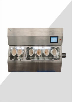
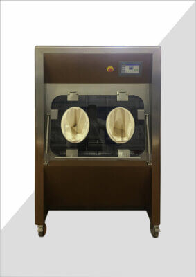
- Closed Restricted Access Barrier System – cRABS — Identify the receiving equipment boundary while mapping existing material, tool and return flows; the listing does not select a transfer arrangement.
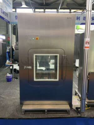
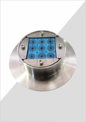
- Biosafety Pass Box — Discuss whether the mapped flow includes a separately supplied pass-through assembly and what its supply boundary would be; suitability requires the project review.
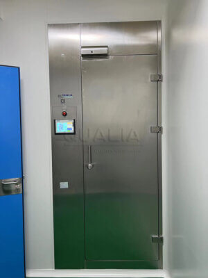
- VHP Pass Box — Open a separate transfer-chamber scope discussion if that alternative is under consideration; no compatibility with the existing cRABS or included decontamination function is assumed.
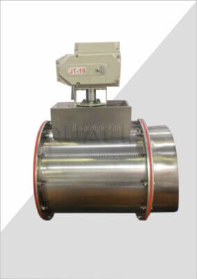
- Biosafety Dunk Tank — Identify a distinct transfer-equipment alternative for the route review where relevant; this navigation neither selects a wet-transfer route nor claims load compatibility.
Record every change part as its own entry, noting how often it moves, what packaging state it arrives in, and what size or weight the transfer provision must accommodate.
The practical reason is dimensional. A cRABS integration project needs to design or select transfer equipment around the largest, heaviest, and most awkward item that will ever cross the barrier, not just around the components that cross it every shift. A tray of filling needles is a manageable pass-through load. A multi-piece nesting fixture or a heavy-format guide rail may require a different access approach entirely—or may reveal that the existing pass-through location cannot serve both routine and change-part traffic without a schedule conflict.
Consider a project where the routine filling process uses a single-door VHP pass box for component transfer and assumes that change parts will follow the same route. During the flow-mapping exercise, the project team finds that the largest format-change assembly is 600 mm on its longest edge and cannot physically fit the pass-through opening. That dimensional conflict, surfaced during mapping, can be designed around. Surfaced during installation, it requires either a rework or a compromised transfer procedure.
Sampling tools and in-process test equipment used only during specific stages of the batch—not at every fill cycle—belong in this category too. They are infrequent enough that they may not appear in a routine batch review, but they cross the barrier, and the cRABS must have a defined provision for them.
Document Waste and Return Flows
Outgoing flows are as important to map as incoming ones, and they are more often left incomplete.
Waste and return traffic includes rejected units, used sampling consumables, spent cleaning materials, used tooling awaiting reprocessing, and any item that exits the controlled zone during or after the batch. Each of these has a direction (outward), a packaging state at the point of exit, a destination, and—crucially—a person or function responsible for the handoff. Under a cRABS arrangement, that responsibility boundary must be explicit because the barrier cannot be assumed to work symmetrically: what works as an entry provision may not be acceptable as an exit route for contaminated or potentially contaminated material.
Where waste currently leaves through the same route used by incoming items, the two directions need to be shown as separate entries in the register. The outgoing purpose and the proposed responsibility boundary should not be assumed to be covered by the same transfer provision as the incoming flow. A project reviewing a shared hatch that currently serves both component entry and waste removal needs to decide, before the barrier is specified, whether that shared use continues, splits into two dedicated points, or is replaced by an integrated waste removal feature. Those are three different equipment configurations, and the decision affects both the cRABS design and the room layout around it.
Return flows deserve attention as a distinct category from waste. Items that leave the zone for reprocessing—reusable tooling, autoclavable components, washable trays—may come back into the process on a later batch. Their outgoing route, their state at exit, and the re-entry provision needed after reprocessing all need to be in the register. If the item leaves contaminated and returns sterile, the entry and exit provisions may be entirely different, and both need to be designed.
Effluent and liquid waste from cleaning operations inside the barrier are a related flow that projects sometimes treat separately from the item-flow register but which belong in the same planning conversation. The question of whether cleaning liquids drain to a contained collection system or to a general floor drain affects the room design and, depending on the materials handled, may carry regulatory or facility management obligations.
Related Reading
- What Existing-Site Information Should Buyers Gather Before Planning a cRABS Retrofit? — Gather the starting process and site information for the flow map.
- What Layout and Access Details Are Needed Before a cRABS Retrofit Design Review? — Connect the mapped flows to the next layout and access discussion.
- What Cleaning and Maintenance Access Must Be Confirmed Before Freezing a cRABS Layout? — Check infrequent access tasks before the layout is fixed.
Assign Transfer Questions Before Integration
An item-flow register is not complete until it surfaces the questions that the project team cannot yet answer—and routes them to the right decision-maker before supplier conversations begin.
The practical step is to review each row in the register and flag the items where the transfer approach is undecided. These are not oversights; they are the design inputs the project still needs to generate. For each flagged item, the register should capture what is known (the item, its current route, its packaging state), what is unresolved (which transfer method, what decontamination step, who is responsible at each side of the barrier), and who in the project has authority to close the question.
Handing the item-flow register to a supplier before requesting a specific equipment arrangement gives both sides a common basis for comparing transfer options—and prevents the supplier from pricing an interface against a description that the project team itself has not yet agreed on.
One issue the register consistently exposes is a gap between how transfers are described in procedure documents and how they are actually performed on the floor. If the observed route differs from the drawing—a tool entering through a door rather than through the designated hatch, a sample leaving in a bag rather than in the labeled container shown in the SOP—both should be captured: the actual route as a data row, and the discrepancy as a note flagged for quality review. A supplier cannot reliably design an interface against conflicting descriptions, and a cRABS integration will make the discrepancy visible even if the project team chooses not to address it formally beforehand.
Packaging state at each transfer point is the last column in the register that projects frequently leave blank. Whether an item arrives heat-sealed in a sterile bag, inside a secondary overwrap, or in a reusable container with a lid determines which transfer equipment is compatible—a VHP pass box, a dunk tank, a simple hatch, or a rapid-transfer port. That column cannot be filled in by inference; it requires someone to watch the actual transfer and record what they see, or to pull the item’s handling specification and confirm it against current practice.
When the register is complete—every item named, routed, packaged, and directionally assigned, with open questions flagged and owners identified—the project team has what it needs to open a productive conversation with a containment supplier like QUALIA: a document specific enough to price against and transparent enough that quality, engineering, and operations are all reading from the same map.
References
- EU GMP Annex 1 – Manufacture of Sterile Medicinal Products (2022) — Use the sterile-manufacturing contamination-control context to identify equipment and site interfaces for review; it supplies no project-specific pass box or cRABS acceptance values.
- EudraLex Volume 4 Annex 15 – Qualification and Validation — Distinguish supplier documentation from project qualification and acceptance decisions; reported conditions and deviations remain specific to the represented system.
- ISO 14644-7:2004 Separative Devices — Frame separative-device requirements and customer–supplier questions within the standard’s verified summary scope; detailed clauses and equipment limits are outside this summary.
- FDA Guidance – Sterile Drug Products Produced by Aseptic Processing (cGMP) — Check whether the project is within sterile aseptic drug-manufacturing guidance before treating its evidence as applicable; the saved summary supplies no retrofit test program.
Frequently Asked Questions
Q: Do rarely used maintenance tools belong in the same information package?
A: Include them when their transfer crosses the proposed integration boundary. Label their infrequent purpose so the project can review them without confusing them with routine production inputs.
Q: Can similar items share one flow entry?
A: Yes, when their form, purpose, route and receiving point are represented accurately. Separate an exception that changes an interface question instead of creating a nominally complete but misleading group.
Q: What if the future process route is not agreed?
A: Show the current route and proposed route as different states. The supplier can then identify conditional interfaces without the draft route being mistaken for an approved process decision.