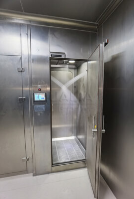
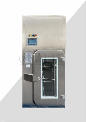
A bio-safety isolation damper installed without a documented maintenance-access plan creates a problem that only surfaces once the surrounding ductwork, insulation, and structural supports are already in place. At that point, a service task that should take minutes can require dismantling finished construction, and a containment verification that should be routine can become uncertain because the test point was never reachable in the first place. Deciding what access the damper needs — and reserving it before the installation locks in — is a planning task, not a field-repair task.
Maintenance tasks that need direct physical access
An isolation damper is not a sealed, maintenance-free component. It carries moving parts — a blade, a shaft, an actuator, and seals — that require inspection, lubrication, functional exercise, and periodic replacement over the equipment’s service life. Each of these tasks has a different physical access requirement, and treating “damper access” as a single generic allowance misses the point. Lubrication may require reaching a specific fitting. Actuator work may require removing a cover and reaching electrical or pneumatic connections. Seal inspection or replacement may require withdrawing the blade assembly from the duct section entirely.
The planning logic that connects these tasks to layout decisions is straightforward in principle: map each inspection, lubrication, actuator, seal, test, and replacement task to the physical access it needs, before finalizing the surrounding installation. Where this mapping is done early, the layout can accommodate it without added cost or disruption. Where it is done after ductwork, insulation, or adjacent equipment are fixed, the same access need becomes a retrofit problem — and in a containment system, a retrofit around an isolation damper is not a simple matter of cutting an access panel, because the panel itself, and the sequence used to open it, becomes part of the containment boundary.
The consequence for the buyer is that maintenance-task mapping belongs in the same design conversation as duct routing, not after it. A damper selected for a given containment duty may have a published service envelope — the space the manufacturer specifies for routine work — but that envelope only protects the maintenance program if the installing team actually reserves it. If a project’s mechanical layout is finalized before this mapping happens, the buyer should treat that as an open risk to confirm, not an assumption to carry forward.
This also affects how maintenance responsibility is assigned later. A task that needs only tool access and a line of sight is different from one that needs component withdrawal and a controlled route for a contaminated part. Classifying each task by its access type, early, is what allows the maintenance plan and the facility layout to be built around the same assumptions.
Clearance around actuators, seals, and test points
| Access need | Space or route to reserve | Maintenance decision supported |
|---|---|---|
| Tools | Working clearance at the relevant inspection, lubrication, actuator, and seal locations | Whether direct service can be completed after surrounding ductwork is installed |
| Test equipment | Reachable test points and space for the applicable equipment | Whether planned functional or leakage retesting can be carried out |
| Component withdrawal | An unobstructed withdrawal path for the component being serviced or replaced | Whether replacement is physically possible within the installed layout |
| Insulation removal | Space to remove insulation where it covers or restricts the service area | Whether the service point remains accessible without relying on unplanned dismantling |
| Contaminated-part removal | A controlled route from the damper service location | Whether removed parts can follow the planned isolation and decontamination conditions |
Service clearance is often planned as a single number — a generic “maintenance zone” around the damper — when it actually needs to answer several distinct questions. Can a technician physically reach the inspection, lubrication, actuator, and seal locations with tools once the duct run is complete? Can test equipment reach the relevant test points, and is there room to operate it there? If the component itself needs to come out for service or replacement, is there an unobstructed path for that withdrawal? Where insulation covers or restricts the service area, is there room to remove it without disturbing adjacent systems? And once a part is removed, is there a controlled route for it to leave the space in a way consistent with the project’s isolation and decontamination conditions?
Each of these is a separate space requirement, and they do not automatically overlap. A duct run might leave enough clearance for hand tools but not for withdrawing a blade assembly along its axis. A damper might be reachable for visual inspection but have its test point obstructed by an adjacent support or by insulation added after commissioning. The failure mode is the same in every case: the access someone assumed was there during design is not there when the task is actually performed.
The condition that changes this judgment is where the damper sits in the system and what surrounds it. A damper in an open mechanical space has very different clearance constraints than one embedded in a tight containment boundary penetration, where adjacent walls, shielding, or interlocked doors limit the available approach. Where space is constrained, the sequence of operations matters as much as the raw dimensions — if insulation removal and component withdrawal both need the same approach path, the plan has to account for them happening in sequence, not simultaneously.
The practical effect is that service clearance planning determines whether direct servicing is possible at all once installation is complete, or whether a maintenance event will require undoing parts of the installation first. This is also where the contaminated-part removal route has to be defined, so that what leaves the damper location follows the same isolation and decontamination logic that governs the rest of the intrusive work.
Safe isolation and decontamination before intrusive work
| Work context | Control to establish | Applicability boundary |
|---|---|---|
| Intrusive work on the blade, shaft, or seals | Define the isolation and decontamination conditions before work begins | The required conditions and method need project-specific confirmation |
| Defined maintenance or renovation events in a BSL-3 facility | Check the BMBL decontamination provisions for the planned event | The guidance is risk-assessment and containment-level context, not a universal decontamination cycle |
| Specified circumstances in a BSL-4 suit facility | Check whether validated gaseous or vapor decontamination applies | The provision applies in specified circumstances and does not establish one universal cycle |
Before any intrusive work touches the blade, shaft, or seals of an isolation damper, the maintenance plan needs to define the isolation and decontamination conditions that apply. This is a different question from physical access — a technician can have a perfectly clear path to the component and still be unable to proceed safely or validly until the system has been brought into a defined, controlled state.
What that state requires depends heavily on where the damper sits and what it protects. A damper serving a containment boundary carries different isolation logic than one in a less critical duty, and the applicable decontamination method is not interchangeable between contexts. The CDC/NIH Biosafety in Microbiological and Biomedical Laboratories (BMBL) 6th Edition addresses this directly for laboratory settings: BSL-3 facility provisions call for decontamination tied to defined maintenance or renovation events, and BSL-4 suit-facility guidance includes validated gaseous or vapor decontamination under specified circumstances. Neither of these establishes a universal decontamination cycle that applies regardless of project or event type — they describe risk-assessment and containment-level context that has to be matched to the specific maintenance event being planned.
This is where a conditional distinction matters: where the work is routine inspection or lubrication that does not breach the containment boundary, the applicable control may be far lighter than where the work opens the blade, shaft, or seal path to the contained environment. Treating every service event as requiring the same decontamination sequence either over-controls routine work or, more seriously, under-controls an intrusive one.
The buyer’s task is to have this isolation and decontamination logic written into the maintenance plan before any field work begins, with the applicable method and confirmation step tied to the specific type of intervention and the specific containment context. The Canadian Biosafety Standard, Third Edition, reinforces the same principle from a verification angle: it calls for documented verification after changes, repairs, or modifications that may affect biocontainment, while limiting its pressure-decay requirements to stated scopes rather than applying them universally. What this means in practice is that the project team needs to confirm, for its own facility and damper application, which decontamination method applies, which events trigger it, and which verification step closes it out — none of this transfers automatically from a general reference to a specific installation.
Removal routes for components and temporary containment
Even where service clearance exists at the damper itself, a maintenance event is not complete until the removed component — and any contaminated material associated with it — has a defined route out of the space. This is a distinct planning question from clearance at the component: clearance determines whether a part can be withdrawn from its installed position; the removal route determines where it goes afterward, and under what containment conditions.
The mechanism here is straightforward: a part taken out of an isolation damper serving a containment duty may itself carry contamination, depending on what the damper was protecting against and what work was performed. Moving that part from the service point to a disposal or decontamination location is not a logistics detail — it is part of the containment chain. If the route passes through clean areas, adjacent equipment, or spaces not designed to receive a potentially contaminated item, the plan has a gap regardless of how well the damper itself was serviced.
The condition that changes this requirement is the containment duty of the installation and the nature of the work performed. Routine lubrication that never breaches the contained boundary may not generate a contaminated part at all. Replacement of a seal or blade component that has been in direct contact with the contained environment is a different case, and the removal route needs to reflect that difference — potentially requiring temporary containment measures, a defined path, or coordination with other controlled operations happening nearby.
This is also where the maintenance plan has to anticipate conflicts with the facility’s operational state. A removal route that works when the surrounding process is shut down may not be available during partial operation. Where a project expects maintenance to occur without a full facility shutdown, the removal route needs to be planned around that constraint from the outset, not worked out improvisationally when the need arises. Confirming this route, and the temporary containment measures it depends on, is part of the same planning exercise that defines clearance and isolation conditions — they are not independent decisions.
Inspection, retest, and spare-part planning over the life cycle
| Life-cycle event | Planning or verification action | Decision boundary |
|---|---|---|
| Inspection or lubrication | Keep the task’s physical access and tool clearance available | The access needed depends on the task and installed configuration |
| Actuator, seal, or other component replacement | Confirm the service clearance, withdrawal path, and controlled route for removed parts | Intrusive blade, shaft, or seal work also requires defined isolation and decontamination conditions |
| Change, repair, or modification that may affect containment | Document the inspection and perform the applicable functional or leakage retest | The applicable test and acceptance basis require project-specific confirmation |
| Pressure-decay verification | Confirm that the planned verification falls within the stated scope of the applicable requirement | The Canadian standard does not establish a universal damper test method or acceptance value |
| Spare-part planning | Identify the component that may require replacement and confirm its access and withdrawal needs | Part selection and quantity require project-specific confirmation |
Maintenance access planning does not end once a damper is installed and commissioned; it continues through every subsequent inspection, repair, and replacement event across the equipment’s service life. The planning logic shifts slightly at this stage, from “can the task be physically performed” to “what does this event require in terms of documentation and verification.”
Routine inspection or lubrication generally needs only the physical access and tool clearance established at the outset — the task itself does not usually change the verification basis. Replacement of an actuator, seal, or other component is a different case: it requires confirming that the service clearance, withdrawal path, and controlled removal route are still valid for the specific part being replaced, and if the work is intrusive to the blade, shaft, or seal, it also falls under the isolation and decontamination conditions already established for that type of work.
The more consequential trigger is any change, repair, or modification that may affect containment performance. Here, the maintenance plan needs to call for documented inspection and the applicable functional or leakage retest — a direct extension of the verification principle in the Canadian Biosafety Standard, which calls for documented verification after changes, repairs, or modifications that may affect biocontainment. What test applies, and what the passing criteria are, is not something a general reference can settle; it requires project-specific confirmation tied to the damper’s actual duty and the facility’s qualification basis. Where a project also references pressure-decay verification, the same standard limits that requirement to stated scopes — it does not establish one universal damper test method or acceptance value, so the buyer needs to confirm whether and how that verification applies to the specific installation.
Spare-part planning follows the same logic as the access mapping done at the design stage: identify which components are realistically subject to replacement over the service life, and confirm that their access and withdrawal needs are still met by the as-built layout, not just the as-designed one. Field conditions, insulation added after commissioning, or adjacent equipment installed later can all erode the clearance that was originally planned. ISO 14644-4:2022 frames cleanroom life-cycle planning in similar terms — covering design, construction, start-up, and ongoing maintenance considerations — though it addresses cleanroom scope generally and does not provide damper-specific design or acceptance criteria, so it supports the planning principle without substituting for a project-specific maintenance specification. Where QUALIA supplies the isolation damper for a given project, the configuration and service envelope documented for that unit becomes a direct input to this life-cycle plan, helping the project team align spare-part, access, and retest intervals with the equipment actually installed rather than with generic assumptions.
Frequently Asked Questions
Q: When should isolation damper maintenance access be finalized?
A: Finalize it during layout planning, before surrounding ductwork and insulation can block service. Map every planned inspection, lubrication, test, actuator, seal, and replacement task to the working space or removal route it requires.
Q: How can a project team judge whether the reserved service clearance is sufficient?
A: Check the installed layout against each physical need: tool use, test-equipment placement, access to test points, component withdrawal, insulation removal, and controlled removal of contaminated parts. Clearance is sufficient only when the relevant tasks can be completed in that specific configuration.
Q: What must be established before work on the blade, shaft, or seals begins?
A: Define the isolation and decontamination conditions for the planned work before it starts. Select those conditions from the facility’s containment level, risk assessment, and applicable project requirements rather than assuming one decontamination cycle applies to every maintenance event.
Q: Does every repair require a leakage retest?
A: A change, repair, or modification that may affect containment should trigger documented inspection and the applicable functional or leakage retest. The project must identify the relevant test method, scope, and acceptance basis because the supplied standards do not establish one universal damper test or acceptance value.
Q: What should the maintenance plan record for future component replacement?
A: Record the component to be serviced, its access and withdrawal needs, the route for removed parts, the required isolation and decontamination conditions, and any inspection or retest triggered by the work. Spare-part selection and quantity should then be confirmed for the installed configuration.