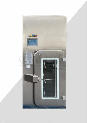
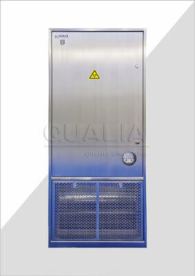
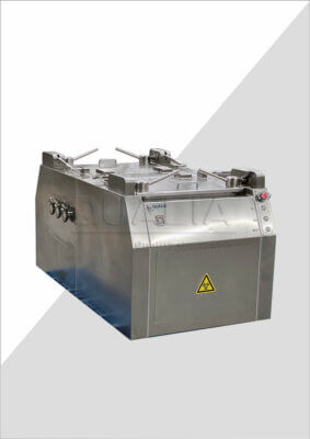
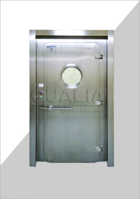
An isolation damper that passes the wrong airflow mode or lacks shutoff margin at the actual differential pressure will not reveal that mismatch until the system is commissioned and already constrained by duct geometry poured in concrete or framed into a wall. Sizing decisions made before layout freeze determine whether the damper fits the space, holds the required pressure differential, and can still be serviced once the facility is operating. Getting these inputs right before supplier engagement changes what the supplier can quote and what the project team can verify later.
Design airflow modes and allowable system resistance
A damper does not operate at one condition. Supply, exhaust, and any standby or decontamination airflow mode each impose a different velocity and pressure profile across the same casing, and the damper has to perform across all of them, not just the mode that happens to be the design basis for the fan selection. Where a facility runs a single steady-state airflow mode with no alternate duty, the sizing problem is comparatively simple: pick a damper whose resistance at that one flow rate fits within what the fan system can deliver. Where the facility cycles between normal operation, a reduced-flow or standby mode, and a decontamination or isolation mode, the damper has to be evaluated at each of those airflow values separately, because the mode with the lowest flow is not necessarily the one that produces the highest resistance relative to what the fan can accommodate.
This matters because allowable system resistance is not a property of the damper alone. It is the resistance budget the fan system has left over after accounting for every other component in the duct run. A damper sized correctly in isolation can still exceed the system’s allowable resistance once it is added to a duct that already carries filters, coils, or other dampers consuming part of that budget. The practical consequence is that damper sizing cannot be finalized from the damper’s own pressure-drop curve alone; it has to be checked against the resistance the fan system can actually absorb at each design airflow mode, including whichever mode produces the tightest margin.
The causes behind elevated resistance across a damper are worth separating from the sizing question itself, since a damper that passes commissioning at one flow condition can still show rising resistance over time for reasons unrelated to initial sizing, a distinction covered in the discussion of what causes pressure drop in bio-safety dampers. For sizing purposes, though, the question is narrower: does the proposed damper, at every design airflow mode the facility will actually use, fall within the resistance the fan system has been designed to accommodate across that point in the duct run. If the facility’s airflow modes have not yet been fully defined, that gap has to be closed before a supplier can propose a sizing with any confidence, because a damper sized to one assumed mode may fail the resistance check once the real operating envelope is confirmed.
Free-area effects behind nominal damper dimensions
The nominal size of a damper, the dimension used to specify it against a duct opening, describes the casing, not the opening available for air to pass through. Inside that casing, the blades themselves, their seals, and the internal frame that holds the assembly together all occupy cross-sectional area that would otherwise be open flow path. The result is that usable flow area is always smaller than the nominal dimension suggests, and the gap between the two is not fixed; it depends on the specific blade and seal configuration of the damper being proposed.
This matters directly for sizing because a damper selected by matching its nominal dimension to the duct size can still be undersized in terms of actual flow area, which means the real velocity and resistance across it will run higher than a calculation based on nominal dimensions alone would predict. Where the project has generous space allowance and flexible duct routing, this effect is manageable by stepping up to a larger nominal size and absorbing the difference. Where the installation is constrained by a fixed duct penetration, a tight mechanical room, or an existing opening that cannot be enlarged, the free-area shortfall becomes a binding constraint rather than a design margin, because there is no larger nominal size available to compensate.
The practical implication is that any resistance or velocity calculation used to support the sizing decision should be built on the actual usable flow area of the specific damper under consideration, not the nominal casing dimension used for procurement reference. This is also where the airflow-mode analysis and the free-area analysis intersect: a damper that appears to meet the resistance budget at a given design airflow, when evaluated against nominal dimensions, may not meet it once the real flow area is substituted into the calculation. Confirming which figure a proposed sizing is based on, nominal casing dimension or usable flow area net of blades, seals, and frame, is a distinction worth resolving before accepting a sizing proposal rather than after installation, since the shortfall is not something a site team can correct once the damper is in place.
Shutoff pressure and actuator torque inputs
Shutoff differential pressure is the pressure the damper’s blades must hold closed against without leaking past an acceptable threshold, and it is not a single value for most containment-relevant installations. Normal shutdown, where the system is brought down under controlled conditions, typically presents a different differential than a failure response, where the damper may need to close against whatever pressure condition exists at the moment of failure rather than one anticipated in advance. A decontamination isolation condition, where the damper has to seal a space off from the rest of the system during a decontamination cycle, can present yet another differential, depending on how that cycle is run.
Each of these conditions places a distinct demand on the damper’s seal design and, more directly, on the actuator responsible for driving the blades to the closed position and holding them there. Actuator torque has to be sufficient not just to move the blades under no-load conditions but to seat them against the specific differential pressure present in whichever isolation condition is being evaluated, and to maintain that seating for as long as the condition requires. An actuator sized against only the normal shutdown differential may be undersized for a failure-response condition if that condition involves a higher differential than the normal case, which is why each isolation condition the project defines needs to be checked against actuator duty individually rather than assuming the most routine condition governs.
Where a facility’s failure-response and decontamination isolation conditions have not yet been characterized in terms of their expected differential pressure, that gap directly limits how confidently actuator duty can be confirmed, because torque sizing follows from the pressure condition it has to resist. This is a case where the consequence of an unresolved input is not a matter of degree but of whether the actuator will seat and hold at all under the condition it is meant to protect against. Defining each isolation condition’s differential pressure, even where the numeric values are still being finalized elsewhere in the project, is what allows actuator duty to be checked against something concrete rather than assumed.
Flange, test-port, and service-envelope allowances
The damper’s own footprint is only part of what the installation location has to accommodate. Flanges add dimension beyond the casing at both ends of the unit. The actuator, depending on its mounting position and the travel it needs to operate the blades, extends outward from the duct in a direction that has to be accounted for separately from the duct run itself. Test ports, where the project requires in-place verification of the damper’s performance, need direct access without obstruction, which means the space around the installed unit has to allow for instrumentation to be inserted and read without disturbing the damper or adjacent ductwork. Insulation, where the duct run is insulated, adds further dimension around the casing that a space allowance based on bare duct size will not capture.
Where a facility has generous mechanical space around the planned installation point, these allowances are a drafting exercise: confirm the dimensions and route the duct accordingly. Where the installation point sits in a tight interstitial space, a congested mechanical room, or a wall penetration shared with other services, each of these allowances competes for the same limited volume, and a design that accounts for flanges and actuator travel but overlooks test-port access or insulation thickness can produce a damper that fits on paper but cannot be instrumented or maintained once installed.
The service-envelope question extends beyond the installed condition to what happens when the damper eventually needs to come out. A damper that was lowered into position during initial construction, before adjacent structure or ductwork was completed, can end up in a location with no practical removal route once the facility is finished and operating. Confirming at the sizing stage that a removal path exists, one that does not require dismantling permanent structure or adjacent equipment, is part of the same envelope planning that governs flange and actuator clearance, and it is harder to correct after the fact than any of the other allowances, because the installation is otherwise complete and operating.
Sizing data suppliers need to confirm before approval
| Sizing input | Project data to provide | Supplier confirmation before approval |
|---|---|---|
| Design airflow and resistance | Airflow for every design mode and the resistance the fan system can accommodate across the damper | The proposed damper sizing uses the stated airflow and resistance inputs |
| Nominal dimensions and flow area | Duct geometry, nominal casing dimensions, and any applicable space constraint | Usable flow area accounts for blades, seals, and internal frames rather than relying on nominal casing dimensions alone |
| Shutoff and actuator duty | Shutoff differential pressure for normal shutdown, failure response, and decontamination isolation | Actuator duty is checked against each stated isolation condition |
| Installation envelope | Allowances for flanges, actuator travel, test ports, and insulation | The proposed casing and actuator arrangement fits within the stated envelope |
| Service access | The practical removal route available at the installation location | The proposed arrangement can be removed through the stated route |
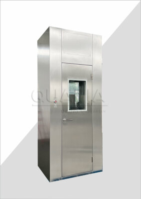
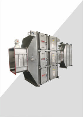
The sizing inputs discussed above do not stand alone from the supplier’s side of the process. Each one becomes something a supplier has to evaluate against the specific damper configuration being proposed, and the sizing proposal is only as reliable as the project data it was built from. Airflow modes and resistance values, usable flow area assumptions, shutoff differential pressure for each isolation condition, and installation-envelope allowances together form the basis a supplier needs in order to confirm that a given damper, such as the configurations available in Qualia’s bio-safety isolation damper line, is actually appropriate to the project rather than a nominal match on duct size alone.
When this information is assembled and submitted for configuration or quotation review, the supplier’s task is to check the proposed sizing against each input individually: whether the damper’s resistance at the stated airflow modes falls within what the fan system can accommodate, whether the usable flow area of the specific blade and seal configuration supports the flow and velocity the project requires, whether the actuator can develop and hold the torque needed for each isolation condition’s differential pressure, and whether the casing and actuator arrangement fits within the stated flange, test-port, and service-envelope allowances including the removal route. Where any of these inputs is incomplete, the confirmation the supplier can offer is limited accordingly; a sizing proposal built on an assumed airflow mode or an unconfirmed removal route carries that assumption forward into the proposal itself.
Project data that is specific rather than general supports a tighter confirmation. A stated resistance budget drawn from the actual fan system, rather than a general assumption about available margin, lets a supplier check the proposed damper against the real constraint instead of a placeholder. A stated differential pressure for each isolation condition, rather than a single assumed worst case, lets actuator duty be checked against the condition that actually governs rather than an estimate. Where this data is still being developed elsewhere in the project, submitting the sizing request with the gaps identified, rather than filled with assumptions, allows the supplier to flag exactly which confirmations remain open rather than returning a proposal that appears complete but rests on unstated assumptions the project team never agreed to.
Frequently Asked Questions
Q: Can an isolation damper be sized from nominal duct dimensions alone?
A: No. The selection should also use the airflow for every design mode, the resistance the fan system can accommodate, and the usable flow area after blades, seals, and internal frames are considered. Ask the supplier to confirm the proposed sizing against those inputs rather than the casing dimensions alone.
Q: Which operating conditions need to be included in the actuator check?
A: Include each project condition that requires isolation, such as normal shutdown, failure response, and decontamination isolation. State the shutoff differential pressure and required actuator duty for each condition so the supplier can verify them separately before approval.
Q: What should be checked if the nominal damper fits the duct but installation space is tight?
A: Check the complete installed and service envelope. Account for flanges, actuator travel, test ports, insulation, and the route needed to remove the proposed arrangement; a casing that fits the duct can still be impractical to install or service.
Q: How should unresolved sizing inputs be handled before approval?
A: Mark each unresolved airflow mode, resistance allowance, shutoff condition, space constraint, or removal route as an open project input. Do not treat a proposal as fully confirmed until the supplier has checked the final values and arrangement against the updated sizing brief.
Q: Does supplier confirmation of the damper size complete the facility’s qualification requirements?
A: No. Supplier confirmation supports the equipment selection, while the project still needs predefined acceptance criteria and verification suited to its facility and applicable qualification framework. Record any deviation from those criteria and resolve it through the project’s approval process.