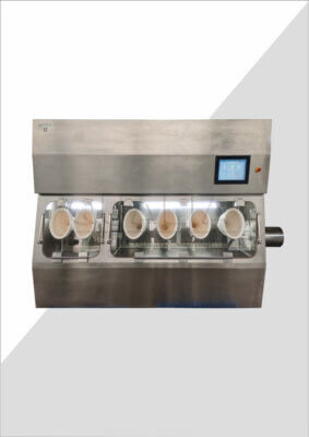
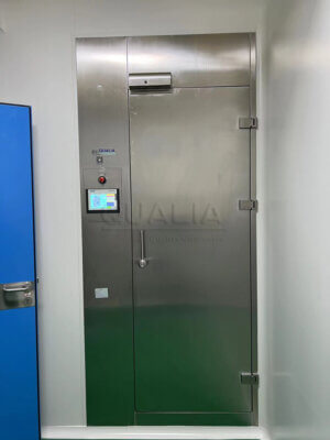
A fixed VHP decontamination system rarely fails because the generator cannot produce vapor-phase hydrogen peroxide at the required concentration. It fails, or stalls in qualification, because the control logic governing doors, dampers, interlocks, and BMS communication was never fully specified before the project reached FAT. Deciding what belongs in the local controller, what belongs in the BMS, and what must be provable at every cycle transition is a design question that has to be answered early, not discovered during commissioning.
Control Design Begins with the Fixed VHP State Model
A fixed VHP cycle is not a single operation; it is a sequence of distinct states, each with its own entry conditions and exit conditions. Dehumidification, conditioning, gassing, dwell, aeration, and return to normal room state each depend on a defined set of physical conditions being true before the controller allows the next transition. The practical design task is identifying, for each state boundary, which doors must be closed or sealed, which dampers must be in a specific position, which fans must be running or stopped, which valves must be open or shut, which sensors must report within their required condition, and which room access points must be secured.
This state model is the foundation for everything that follows in the control design, because interlocks, alarms, and BMS handshakes only make sense in reference to a specific transition they are protecting. Where the state model is incomplete or ambiguous, the interlock list inherits that ambiguity, and the gap tends to surface late in the project, when it is harder and slower to resolve.
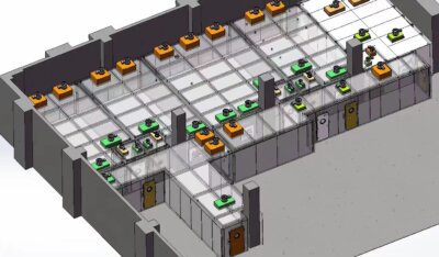
The condition that changes the shape of this model is the configuration of the enclosure or room being decontaminated and its relationship to surrounding spaces. A fixed system serving a single isolator has a simpler boundary than one serving a suite with multiple access points, pass-throughs, or adjoining rooms that share ductwork or utilities. As the number of physical boundaries grows, so does the number of conditions that must be proven before a transition, and the number of components the control system must monitor or command at each step.
Buyers preparing a URS benefit from mapping the physical boundary first, independent of vendor-specific control architecture, because that boundary map is what determines how many states the cycle actually needs and how many permissives attach to each transition. A supplier reviewing a project against something like the VHP Hydrogen Peroxide Generator Type I will configure cycle control around this same boundary logic, so defining it clearly before that review shortens the distance between what the buyer asks for and what the configuration can confirm.
This is also where the buyer should decide how much of the state model is fixed by the process itself versus how much is a facility-specific choice. A gassing dwell condition tied to a validated cycle parameter is a process decision; a door sequence tied to how the room is accessed during normal operation is a facility decision. Keeping these two categories distinct avoids a control design that treats facility convenience as if it were a process requirement, or the reverse.
Permissives and Interlocks That Protect Each Cycle Transition
Once the state model identifies which doors, dampers, fans, valves, sensors, and access points matter at each transition, the next decision is how each of those elements is proven and protected. A permissive is a condition that must be confirmed true before the controller allows a transition to proceed. An interlock is a control action that prevents or forces a state in response to a condition, independent of whether an operator or the BMS requests otherwise. The distinction matters because a permissive is a gate on forward progress, while an interlock is an active constraint that can override a request.
Where a door must be proven closed before gassing begins, that is a permissive. Where a damper is forced to a fail-safe position the instant a sensor reports a condition outside its required range, that is an interlock. Both protect the same transition, but they fail differently, and a verification plan has to test them differently. A permissive failure typically prevents the cycle from advancing; an interlock failure actively changes the state of equipment, which has consequences for whatever else depends on that equipment’s position.
The condition that changes how many permissives and interlocks a project needs is how much the fixed VHP system shares infrastructure with other functions in the space. A damper that serves only the VHP cycle is simpler to interlock than one that also participates in normal HVAC operation, because the second case requires the control logic to arbitrate between two different sets of demands on the same physical component. Similarly, a door that is also a personnel access point during normal operation carries interlock requirements that a dedicated service door does not.
Buyers should resist treating this list as a single undifferentiated set of “safety items.” Each permissive and interlock has an owner: the equipment or system responsible for proving the condition or taking the action. Where that ownership is not assigned clearly during design, it tends to default to whichever controller happens to have access to the signal, which is not the same as whichever controller should logically own the decision. This becomes the central question the next section addresses, because it is where local control and BMS responsibilities are most often confused.
BMS Handshakes Versus Local Controller Responsibilities
| Interface item | Supported role | Boundary to state |
|---|---|---|
| Safety-critical permissive | Proves a required condition before a cycle transition | Keep the permissive decision separate from status sent to the BMS and identify its owner |
| Equipment interlock | Protects a cycle transition through control action | Keep the interlock action separate from BMS status reporting and identify its owner |
| BMS status signal | Communicates process or equipment status to the BMS | Receiving status does not by itself establish ownership of a permissive or interlock |
| BMS handshake | Defines the exchange at the BMS interface | State what each side sends or receives and who owns the associated control decision |
The most common source of ambiguity in fixed VHP control design is treating BMS communication as if it were equivalent to control ownership. A BMS can display a door status, a damper position, or a cycle phase without being the system that decided those conditions were met. Receiving a status signal is not the same as holding the permissive or executing the interlock. Where this distinction is blurred, troubleshooting becomes difficult, because a status discrepancy at the BMS screen does not tell the operator whether the local controller, the field device, or the communication link is the source of the problem.
The general principle is that safety-critical permissives and equipment interlocks belong to the controller that can directly sense the field condition and directly command the response, while the BMS role is to exchange status and, where defined, issue requests that the local controller independently validates before acting. A handshake at the BMS interface should specify exactly what each side sends, what each side receives, and which side owns the resulting control decision. Where a handshake is defined only as “BMS confirms door closed” without stating which controller performed that confirmation and under what conditions it is considered valid, the interface is incomplete.
The condition that changes how this boundary is drawn is the level of trust the project places in the BMS network as a control path versus a monitoring path. Where the BMS is used only for monitoring, supervisory override, and data historian functions, the local controller retains full authority over permissives and interlocks, and BMS communication loss has limited effect on cycle safety. Where the BMS is given any role in commanding a cycle action, every such command needs its own validation logic in the local controller, because a networked request carries different failure modes than a hardwired signal.
This boundary question connects directly to what a project needs to specify about equipment and alarm evidence during procurement. A supplier responding to a request for controls and interlock requirements needs to know, for each permissive and interlock, whether the BMS is expected to participate in the decision or only observe its outcome, because that determines how much of the control logic resides in the local PLC versus how much is exposed at the BMS interface. Leaving this undefined in a request for quotation tends to produce proposals that are not directly comparable, because each supplier will have made its own assumption about where the boundary sits.
Alarm, Abort and Recovery States to Define in the URS
| URS control point | Definition needed | Decision boundary |
|---|---|---|
| Alarm cause | The event or condition that initiates the alarm | Connect the initiating condition to the required response |
| Alarm response | The required response to the alarm | Make the intended handling explicit before testing |
| Safe state | The state required when the alarm occurs | Define the condition the controls must establish or maintain |
| Acknowledgment | How the alarm is acknowledged | Keep acknowledgment distinct from authority to reset |
| Reset authority | Who may reset the alarm | Define the authorization boundary for reset |
| Cycle release effect | Whether and how the alarm affects cycle release | Make the release consequence explicit |
| Abort state | The required control result after an abort | Provide an expected state that can be challenged in testing |
| Power recovery state | The required behavior after power recovery | Provide an expected recovery condition that can be challenged in testing |
An alarm specification that lists only the condition that triggers the alarm is incomplete. A usable alarm definition for a fixed VHP system specifies the cause, the required response, the safe state the controls must establish or maintain, how the alarm is acknowledged, who holds authority to reset it, and whether and how the alarm affects cycle release. Each of these is a separate decision, and treating them as a single undifferentiated “alarm list” entry tends to produce ambiguity exactly where clarity is needed most, at the point of abnormal operation.
Acknowledgment and reset are frequently conflated but serve different purposes. Acknowledgment confirms that an operator has seen and recognized the alarm; it does not by itself restore the system to a state where the cycle can proceed. Reset authority determines who is permitted to clear the alarm condition and allow progress to resume, and this authority can reasonably be assigned differently depending on the severity of the condition and its relationship to operator or environmental protection. Where acknowledgment and reset are treated as the same action, the control system may allow progress before the underlying condition has actually been resolved.
Abort and power recovery states deserve particular attention because they define behavior outside the normal cycle sequence. An abort state is the condition the controls must establish when a cycle is deliberately or automatically terminated before completion; a power recovery state defines what the system does when power returns after an interruption. Neither of these should be left to default behavior, because the consequence of an undefined abort state is a system that may leave doors, dampers, or valves in an undetermined position, and the consequence of an undefined power recovery state is a system that may resume a cycle sequence without confirming that the conditions that justified an abort have been addressed.
The condition that changes how these states should be defined is whether the recovery path is expected to be automatic or dependent on manual intervention. Where a project requires that any abort or power loss during gassing always routes to a state requiring manual confirmation before re-entry, that requirement needs to be explicit in the URS, because a controller designed without that requirement may default to automatic resumption once conditions are nominally satisfied. These behaviors cannot be verified unless they are specified; a test plan can only challenge what the URS defines as the expected outcome.
GMP Records, Access and Audit Trail Boundaries
| Record or control area | Risk-based definition | Boundary to preserve |
|---|---|---|
| Recipes | Determine their GMP relevance and required record scope | Apply controls according to documented risk |
| Setpoint changes | Determine which changes are GMP-relevant and must be recorded | Do not assign every change the same data-integrity role |
| Audit trails | Define where GMP-relevant changes require traceability | Scope the audit trail to the documented risk and user requirements |
| User access | Define access controls for GMP-relevant functions and records | Match access control to the role of the data and function |
| Backup | Define backup controls for stored GMP-relevant data | Limit the requirement to the supported computerized-system scope |
| Record retention | Define retention for the GMP-relevant records in scope | Base the retention boundary on the documented requirement |
| Facility events | Assess each event’s GMP and data-integrity role | Do not treat every facility event as equally GMP-relevant |
Not every signal passing through a fixed VHP control system carries the same data-integrity weight, and treating them as if they did produces a validation burden that does not match the actual GMP risk. EudraLex Volume 4 Annex 11 establishes that computerized-system controls, including audit trails, stored data, backups, and access, follow a risk-based approach tied to documented user requirements, rather than a uniform rule applied to every system function.
Applied to a fixed VHP system, this means the project team needs to determine, function by function, which elements are GMP-relevant and which are facility-operational. A recipe parameter that affects the validated decontamination cycle sits differently than a facility-level setpoint adjustment made for comfort or energy reasons. A setpoint change that could affect cycle efficacy needs traceability in a way that a change unrelated to the validated process may not. Audit trail scope, under Annex 11’s risk-based framing, should be drawn around the GMP-relevant changes identified through this assessment rather than captured indiscriminately across every parameter the controller can log.
User access control follows the same logic: access should be structured according to the role of the function being protected, so that the ability to change a GMP-relevant recipe parameter is governed differently than the ability to view a facility status screen. Backup requirements apply to the GMP-relevant stored data identified in this scope, and record retention is defined against the same boundary rather than against the system’s full data output.
The condition that changes where this boundary sits is the extent to which the fixed VHP system’s facility-side functions are separated from its cycle-controlling functions. Where a single controller handles both facility monitoring and the validated decontamination cycle, the risk assessment needs to examine every function the controller performs to identify which fall inside GMP scope. Where the two are architecturally separated, the assessment is more contained, because facility events outside the cycle-controlling function carry a different data-integrity role from the outset. Either way, the assessment itself, not the system’s technical capability to log everything, is what determines the boundary, and that assessment needs to be documented in a form that can be reviewed alongside the URS.
Verification Scenarios for FAT, SAT and OQ
| Verification stage | Supported role | Evidence decision |
|---|---|---|
| FAT | Justified vendor testing before delivery | Document the tested scope and the rationale for using the FAT evidence |
| SAT | Supplementary testing after receipt | Use documented rationale and the effects of transport or installation to decide what needs site confirmation |
| OQ | Challenge testing of operating functions | Use applicable URS-defined scenarios such as loss of communication, sensor failure, power recovery, abort, and manual override as challenge inputs |
The control behaviors defined across the state model, the permissive and interlock list, the BMS boundary, and the alarm and recovery specification only become meaningful once they are challenged under test conditions that mirror how the system will actually fail or recover in service. EudraLex Volume 4 Annex 15 allows justified vendor FAT to stand in place of repeated testing after delivery, while distinguishing IQ installation checks from OQ challenge testing, and permits supplementary SAT where transport or installation could plausibly affect functionality.
This framework gives the project team a basis for deciding, scenario by scenario, where testing belongs. A FAT conducted at the vendor’s facility can reasonably challenge control logic that does not depend on the final installation environment, such as the sequencing of permissives and interlocks defined in the URS, provided the test configuration faithfully represents the delivered system. A SAT becomes necessary where the specific scenario depends on conditions that only exist once the system is installed, such as how a BMS handshake behaves across the actual site network, or how a sensor responds in its final physical location. The decision about which scenarios need repeating at SAT, under Annex 15’s framing, rests on documented rationale tied to whether transport or installation could affect the result, not on a blanket assumption that every test must be repeated on site.
OQ challenge testing is where the abnormal-condition behaviors defined in the URS are actually exercised: loss of communication between the local controller and the BMS, failure of a sensor relied on for a permissive, power interruption and recovery, cycle abort, and manual override. Each of these scenarios should trace back to a specific URS-defined expected outcome; a loss-of-communication test is only meaningful if the URS already states what the local controller is supposed to do when that communication is lost, and a manual override test is only meaningful if the URS defines who holds that authority and what state results.
Where a project has already assembled site-level verification expectations for utilities, controls, alarms, and VHP-related interfaces as part of broader SAT planning, the fixed VHP control scenarios described here need to align with that same framework rather than being treated as a separate exercise, because the same communication and power-recovery conditions often affect multiple integrated systems at once. Projects that enter FAT without having resolved which scenarios belong at FAT versus SAT versus OQ tend to discover the gap only when a test cannot proceed because the expected outcome was never written down, which is a URS problem surfacing late rather than a testing problem.
Frequently Asked Questions
Q: What project information should be ready before a fixed VHP controls workshop?
A: Prepare the cycle states and transitions, then list the doors, dampers, fans, valves, sensors, and access points whose conditions must be proven at each transition. For every item, identify who owns the control decision, what the BMS sends or receives, and what evidence will confirm the intended behavior.
Q: Does receiving a VHP status signal mean the BMS owns the related interlock?
A: No. A status signal communicates information but does not establish ownership of a permissive or interlock; the interface definition should state what each side sends or receives and where the associated control decision is made.
Q: Can alarm acknowledgment also authorize a reset or cycle release?
A: No. Acknowledgment, reset authority, and the effect on cycle release are separate decisions. Define each one in the user requirements, together with the alarm cause, required response, and safe state, so the behavior can be tested without relying on operator interpretation.
Q: What should be defined before testing communication loss, power recovery, or a sensor failure?
A: Define the expected control state, alarm response, abort consequence, recovery path, reset authority, and any effect on cycle release for each applicable scenario. Those expected results give FAT, SAT, and OQ teams a clear basis for challenge testing.
Q: Does every facility event need the same GMP audit trail and retention controls?
A: No. Use a documented risk assessment to decide which recipes, setpoint changes, facility events, and stored records are GMP-relevant, then define the applicable access, audit trail, backup, and retention controls for that scope.
Q: When can vendor FAT evidence be used without repeating the same test at the site?
A: Use FAT evidence when its tested scope and the rationale for relying on it are documented. Decide what still needs SAT or OQ confirmation by considering whether transport or installation could affect the function and which user-requirement scenarios require site challenge testing.