Cable and conduit routes through a BSL-3 or BSL-4 containment boundary are not a mechanical or electrical afterthought routed once the room layout is fixed. Each penetration is a boundary decision: it changes how the containment envelope is sealed, how future access is managed, and how the wall or barrier assembly performs at that point. Getting the route plan right before construction avoids a wall that has to be reopened, resealed, or re-verified later.
Locate the containment boundary before assigning cable and conduit routes
The containment boundary is a defined line on the plan, not an assumption based on which room looks enclosed. Before any cable or conduit is assigned to a wall opening, that boundary needs to be traced continuously across the layout, including at changes in wall type, at interfaces with adjoining rooms, and at any point where the boundary steps around equipment or structural features. A route that looks like a short, direct path on a mechanical or electrical drawing may in fact cross the boundary at an angle, cross it twice, or run parallel to it without actually penetrating it — and each of these produces a different requirement for how the penetration is built and sealed.
This matters because the boundary, not the room geometry, is what determines which openings need containment-rated treatment. A conduit run that stays entirely on one side of the boundary has different requirements than one that crosses it, even if both runs appear in the same trench or the same cable tray upstream. Where a designer assigns routes from a general services drawing without first confirming where the boundary actually falls, an opening can be sized, sleeved, or scheduled incorrectly — and the error may not surface until commissioning or inspection, when moving the penetration is far more disruptive than specifying it correctly at the outset.
The practical implication is sequencing: boundary tracing has to happen first, as a discrete step, before any individual cable or conduit is committed to a specific wall location. If the boundary shifts during design — because a room is reassigned, an airlock is repositioned, or an interstitial space is added — every route assignment made against the earlier boundary needs to be re-checked, not assumed to still be valid. Where a project involves multiple design disciplines working from a shared floor plan, the containment boundary should be treated as controlled reference information that each discipline reads from the same current version, rather than something each trade re-derives independently. A cable or conduit route schedule that does not reference which version of the boundary drawing it was built against is difficult to audit later, particularly when the two disciplines’ as-built conditions diverge.
Group compatible services while limiting wall openings
Every additional wall opening is an additional point where the containment barrier depends on a seal, a sleeve, or a frame rather than on continuous wall construction. Reducing the total count of openings, by grouping compatible services through a shared transit where the approved design permits it, reduces the number of these dependent points without changing what services the room actually needs. This is a design trade-off rather than a simple reduction: grouping multiple cables or conduits through one opening concentrates risk at that location, so the transit detail at a grouped opening needs to account for all the services passing through it, not just the first one specified.
Whether grouping is appropriate depends on what the approved design actually allows for that project. Some service combinations are compatible within a shared transit; others are not, depending on factors such as the sealing method specified for the transit, the maintenance access each service line requires independently, and whether the services belong to systems that are qualified or serviced on different schedules. A route that groups a service needing periodic access with one that is expected to remain undisturbed for the life of the facility creates a maintenance conflict at that shared opening, since disturbing the boundary seal to reach one service also affects the other.
The number of openings is not itself the objective — a design that eliminates openings by grouping services that should not share a transit trades one problem for another. The design decision is to group where the approved configuration supports it, and to keep each remaining ungrouped opening deliberate rather than incidental. Where a services drawing shows multiple individual conduits converging near the same wall location without an explicit grouping decision, that convergence should be reviewed, not treated as evidence that grouping has already been considered.
Reserve positions for foreseeable cable additions without assuming unlimited re-entry
| Planning status | What the plan should show | Boundary for later use |
|---|---|---|
| Planned cable or conduit route | Assignment to a wall opening | Grouping with other services depends on the approved design. |
| Foreseeable cable addition | An explicit reserved position | A reserve is not an assumption of unlimited re-entry. |
| Empty opening with no reserve identified | No stated reserved position | Do not treat the empty opening as an informal future option. |
A containment wall is not a surface that can be reopened on the same terms repeatedly. Once a penetration has been sealed and the boundary verified, re-entry to add a service later is a controlled event, not a routine one, so a project that anticipates future cable additions needs to decide, at the design stage, which of those additions get an explicit reserved position now rather than being left for a future opening.
A reserved position differs from an empty opening in an important way: a reserve is a location that has been deliberately sized, sleeved, or framed for a specific anticipated service, with that intent documented on the route schedule. An empty opening with no stated purpose is not a reserve — it is an unassigned penetration that happens to exist, and treating it as informal future capacity assumes an option that was never actually designed in. Where the project genuinely expects additional instrumentation, monitoring, or process cabling to be added after initial construction, that expectation should be converted into a specific reserved position with its own sleeve or frame detail, sized for the service it is intended to receive.
This distinction changes how the design team should read the drawing set. A route schedule that shows reserved positions explicitly gives the project a documented basis for later work — the installer knows which opening is available, what it was sized for, and what sealing method applies when it is used. A schedule that relies on unlabeled empty openings gives no such basis, and using one of those openings later requires the same evaluation as adding an entirely new penetration, without the benefit of having planned for it. The number of reserves a project should carry is not a fixed figure; it depends on how confidently the project can identify future service needs at the design stage, and a reserve carried without a specific anticipated use is difficult to distinguish, in practice, from an unplanned opening.
Coordinate opening, sleeve or frame geometry with the actual wall assembly
The size and detail of a penetration cannot be fixed independently of the wall it passes through. Wall assemblies used in containment construction vary in thickness, layering, and material, and the sleeve or frame detail that suits one assembly does not necessarily suit another — a detail correct for a solid wall section may be unsuitable where the same boundary line crosses a service wall, a shaft, or a section with different lining or structural backing. Before an opening size is fixed on the design drawings, the proposed service mix for that opening, the access needed for any later pulls through it, the wall thickness at that exact location, and the sleeve or frame detail all need to be checked against one another as a single set, not approved individually in sequence.
Where these are coordinated late — for example, where an electrical designer fixes an opening size before confirming it against the wall detail at that location — the result can be a sleeve or frame that does not match the actual wall build, requiring rework at installation or a compromise in the sealing detail that was not part of the original design intent. The condition that changes this judgment is the wall assembly itself: a route plan produced from a generic wall type note, without confirming the assembly at each specific crossing point, carries this risk regardless of how carefully the service mix has been planned.
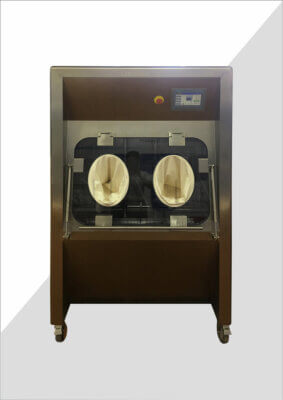
Access for later pulls is part of this same coordination, not a separate consideration. An opening sized only for the cables specified at the time of design, with no allowance for how a cable might later be withdrawn or replaced without disturbing the surrounding seal, forecloses maintenance options that a slightly different sleeve or frame geometry would have preserved. This is where equipment such as a cable or cord port earns its place in the design: a port built to allow controlled passage and re-entry at a defined location gives the project a documented interface for that purpose, rather than relying on a generic sleeve that was not designed with later access in mind. Qualia’s Vacu-Pass Cord and Cable Port is one such component, selected and configured for the specific service and wall condition at a given crossing point; its suitability at any particular location still depends on the wall assembly and service mix confirmed for that project.
Route drawings and interface details to approve before construction
| Review item | Detail to make visible | Coordination use |
|---|---|---|
| Containment-boundary plan | Boundary line at each proposed cable or conduit crossing | Assign the route to the wall opening after tracing the boundary. |
| Route schedule | Each penetration and its adjoining wall interface | Keep crossings identifiable across electrical and mechanical scopes. |
| Opening and sleeve or frame detail | Proposed service mix, access for later pulls, wall thickness, and sleeve or frame detail | Compare these before the opening size is fixed. |
| Reserved positions | Explicit positions for foreseeable additions where the approved design permits | Avoid treating an empty opening as an unstated future option. |
The decisions made in the earlier stages only hold if they are visible on the documents that installers actually build from. A containment-boundary plan that shows the boundary line at each proposed crossing, a route schedule that identifies every penetration individually along with its adjoining wall interface, and an opening detail that reflects the service mix and wall assembly confirmed for that location together form the minimum documentation set that should be reviewed and approved before construction begins.
The risk this stage addresses is a specific one: individual penetrations disappearing inside a general electrical or mechanical scope of work. A contractor drawing that shows conduit routing as part of a broader electrical package, without calling out which runs cross the containment boundary and what interface detail applies at each crossing, gives no one a clear point at which to check that the boundary-specific requirements were actually carried through from design intent to installation. A route schedule that lists each penetration by location, service, and wall interface — distinct from the general trade drawings — keeps that information from being absorbed into scope language that treats all conduit runs as equivalent.
Reserved positions belong in this same review. If a reserve was identified earlier as a deliberate future-use location, it needs to appear on the approved documents with that status stated, so it is built with the sleeve or frame detail it was intended to have rather than left as an unlabeled opening that a later reviewer cannot distinguish from an unplanned gap.
This is also the stage at which the project’s own information about intended service mix, anticipated additions, and wall conditions becomes part of what a supplier can act on. When a project shares its route schedule and boundary plan with a supplier of a component such as a cable or cord port, that information is what allows the port’s configuration to be matched to the actual crossing it will serve, rather than specified generically. Confirming these details before construction — rather than during installation, when a mismatch between drawing and wall condition is far harder to correct — is what keeps the containment boundary’s cable and conduit crossings verifiable as built, consistent with the structural and technical safety measures for BSL-3 laboratories described by the Swiss Expert Committee for Biosafety, recognizing that BSL-4 conditions and the specific wall assembly on any given project still require confirmation against that project’s own design.
Frequently Asked Questions
Q: How can I tell which cable or conduit routes need a containment-wall crossing?
A: Trace the containment boundary on the plan first, then identify where each proposed route crosses it and assign that route to a wall opening. This makes the boundary crossing visible before openings are allocated.
Q: Can several services share one wall opening?
A: Yes, where the approved design permits that grouping. Show the proposed service mix for the opening rather than assuming that different routes can be combined without a project-specific decision.
Q: Does an unused wall opening count as capacity for a future cable?
A: No. Show foreseeable additions as explicit reserved positions where the approved design permits them; an unassigned opening is not an informal promise of future access or unlimited re-entry.
Q: What should be checked before fixing the size of a wall opening?
A: Compare the proposed service mix and access for later pulls with the actual wall thickness and sleeve or frame detail. If those items do not fit the proposed crossing, resolve the route or opening detail before its size is fixed.
Q: What should installers receive to keep each crossing identifiable?
A: Provide a boundary plan and route schedule that identify each penetration and its adjoining wall interface, together with the applicable opening and sleeve or frame detail. This keeps a crossing from disappearing inside a general electrical or mechanical scope.
Q: Can BSL-3 design guidance be used as the final rule for a BSL-4 crossing?
A: No. The cited Swiss guidance is nonbinding BSL-3 advice, and the cited WHO material supplies a general risk-assessment principle rather than cable-route geometry. Confirm the BSL-4 boundary and actual wall detail for the project before settling the crossing design.