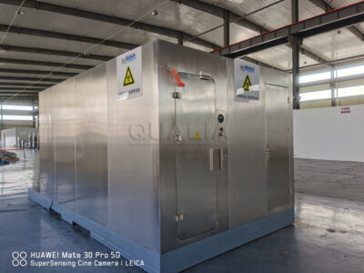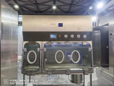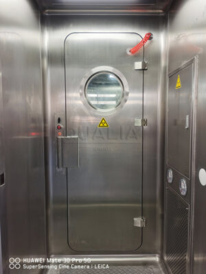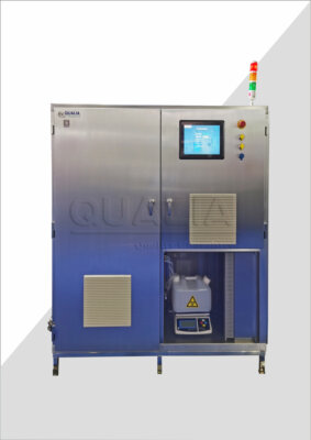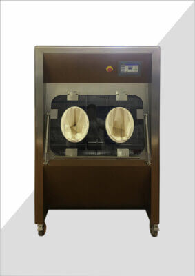
Choosing between membrane filtration and direct inoculation inside a sterility test isolator is not primarily an equipment decision. It is a test-method decision that happens to have equipment consequences. Getting the sequence backward — letting the isolator configuration suggest the method rather than confirming the method before sizing the isolator — creates rework risk in chamber layout, glove placement, and transfer capacity later in the project.
Product and Test-Method Requirements That Frame the Choice
| Informações para a tomada de decisão | Role in the method choice | Limite das evidências |
|---|---|---|
| Applicable compendial procedure | Establishes the applicable sterility-test procedure | Verify the applicable passage before treating method requirements, direct-inoculation rules, values, or compliance conclusions as established. |
| Product-specific method-suitability evidence | Supports the selected method for the specific product | Method suitability must be established for the product rather than inferred from the isolator configuration. |
| Isolator vendor input | Informs configuration after the method and representative workload are defined | The vendor alone should not govern the test-method choice. |
| ISO 13408-6:2021 | May inform general aseptic-isolator principles | It does not specify sterility-test-isolator requirements or the governing test method. |
The sterility test method is a product-and-procedure question before it is an equipment question. The applicable compendial procedure, referenced through sources such as USP General Chapter 71 on sterility tests, establishes which test framework applies to a given product category. Within that framework, method-suitability evidence specific to the product determines whether membrane filtration, direct inoculation, or another approach can be used to demonstrate that the product does not interfere with microbial detection. This evidence has to be generated and evaluated against the product itself; it cannot be inferred from how an isolator is built or from what a vendor’s standard configuration happens to support.
This distinction matters because isolator suppliers work from the chamber side of the problem — barrier integrity, glove positions, transfer systems, bio-decontamination cycles — while the method choice is governed by laboratory and regulatory affairs considerations tied to the product’s formulation, antimicrobial properties, and compatibility with filtration or culture media. Where a product is filterable and does not exhibit inhibitory properties against the test organisms once filtered and rinsed, membrane filtration is commonly the supportable method. Where a product cannot be filtered, or where filtration and rinsing fail to remove inhibitory activity, direct inoculation becomes the route that method-suitability testing would support instead. Neither outcome is something an isolator vendor can establish on the buyer’s behalf.
A related boundary concerns general isolator standards. ISO 13408-6:2021 addresses isolator systems within aseptic processing of health care products, and some of its principles around barrier design and operation may inform general isolator thinking. It does not, however, specify requirements for sterility-test isolators as a category, nor does it determine which sterility-test method applies to a given product. Treating a general aseptic-isolator standard as if it settled the method question — or as if it supplied direct-inoculation rules — would be a misapplication of its scope.
The practical sequencing consequence is this: before any conversation about chamber dimensions, glove count, or transfer airlock sizing, the project team needs the applicable compendial passage confirmed and the product-specific method-suitability data in hand. Isolator configuration should follow from the method, not substitute for the evidence that selects it.
Membrane Filtration Workflow Inside the Isolator
Membrane filtration, once selected as the suitable method for a given product, resolves into a specific physical sequence that the isolator must accommodate from the inside out. The product is introduced into the chamber, transferred through whatever decontamination or pass-through step the project defines, and then passed through a filtration apparatus that retains any microorganisms present on a membrane while the liquid itself passes through. That membrane is then rinsed — a step intended to remove residual antimicrobial or inhibitory activity from the product before the membrane is transferred to a growth medium for incubation.
Each of those stages has a physical footprint and a manipulation profile inside the barrier. The filtration apparatus itself occupies chamber space and needs operator access for assembly, operation, and breakdown. Rinsing fluid containers, their introduction, and their disposal add another layer of material flow that the chamber and its transfer systems must support without compromising the barrier. The membrane-to-media transfer at the end of the sequence is itself a critical manipulation point, since it is the step most exposed to the risk of handling error or contamination if glove access or working space is constrained.
Where a product requires multiple filtration units — because the test design calls for replicate units, multiple containers, or a divided product volume — the equipment and container load inside the chamber multiplies accordingly, and so does the manipulation burden placed on the operator working through isolator gloves rather than open bench conditions. This is a condition that changes the judgment materially: a single-unit filtration workflow and a multi-unit one are not the same design input, even though both fall under “membrane filtration” as a method label. The representative workload — not the method name alone — is what the chamber design actually needs to absorb.
Waste handling follows the same logic. Spent filtration apparatus, rinse fluid containers, and any disposable components generated during the sequence have to move out of the chamber through a waste or transfer pathway without creating a contamination route back into the aseptic space. The volume and nature of that waste stream depends entirely on how the filtration sequence was actually built for the product in question, not on a generic description of membrane filtration as a method.
Direct Inoculation Workflow and Its Handling Demands
Direct inoculation follows a different physical logic, even though it answers the same underlying question of whether the product supports microbial growth when none is intended. Instead of separating microorganisms from the product through a filtration membrane, the product itself — or a defined portion of it — is introduced directly into a growth medium contained in its own vessel, after which that vessel is incubated and later examined for growth.
This removes the filtration apparatus and the membrane-handling step entirely, but it does not reduce the workflow to something simpler by default. The product-to-media transfer becomes the critical manipulation, since the product must be introduced into the media container without compromising the sterility of that transfer. The container set is different from membrane filtration’s apparatus and membrane components: here, the governing items are the product containers themselves and the media containers they are inoculated into, each of which needs its own path into, through, and out of the chamber.
Where a product’s volume or dosing format requires multiple media containers per test unit — for instance where the product is divided across several containers to meet the test design — the inoculation workflow multiplies in the same way a multi-unit filtration workflow does, though the physical items being handled and transferred are different in kind. This is the condition that most affects direct inoculation’s space and intervention profile: the number and size of media containers the chamber must hold, stage, and allow access to during inoculation drives glove-position and working-surface requirements independently of filtration-specific equipment.
Incubation itself does not necessarily occur inside the same isolator chamber used for inoculation, depending on how the project’s facility and equipment are configured, but the transfer of inoculated containers out of the chamber toward incubation is still a step the isolator design has to support without introducing contamination risk at that boundary. Recovery — the later reading of those containers for evidence of growth — depends on the inoculation step having been performed correctly, which places weight on the quality of operator access and manipulation space during the inoculation sequence rather than afterward.
Mapping this sequence in full, rather than treating “direct inoculation” as a single generic step, is what allows a project team to compare its actual space and intervention needs against membrane filtration’s needs on equal terms.
Equipment, Container, Transfer, and Waste Differences
| Dimensão de comparação | Membrane filtration: establish for the project | Direct inoculation: establish for the project | Design question informed |
|---|---|---|---|
| Equipamentos | Actual filtration equipment required inside the barrier | Actual equipment required for product handling and media containers | How much chamber space the selected method needs |
| Containers | Container set used through filtration and rinsing | Product and media-container set used through inoculation, incubation, and recovery | How containers affect chamber layout and glove positions |
| Manipulations | Actual filtration and rinsing manipulations | Actual product-handling and inoculation manipulations | Where operator access and interventions occur |
| Transferências | Equipment, containers, and materials moved through the filtration workflow | Product, media containers, and materials moved through the direct-inoculation workflow | What transfer capacity the representative workload requires |
| Resíduos | Waste steps in the filtration workflow | Waste steps in the direct-inoculation workflow | How waste handling affects space, transfers, and interventions |
| Representative workload | Workload using the complete membrane-filtration sequence | Workload using the complete direct-inoculation sequence | How the selected method affects chamber size and bio-decontamination loads |
Once both workflows have been mapped in their own terms, the comparison between them becomes a structured one rather than an impression. Membrane filtration brings filtration apparatus, membrane handling, and rinse fluid management into the chamber; direct inoculation brings product and media containers and a transfer-to-incubation step instead. Neither method is inherently larger or more demanding than the other in the abstract — the determining factor is the representative workload the selected method generates for the specific product and test design.
This is where project-specific detail has to replace generic method comparison. The equipment each method requires inside the barrier, the container sets each method moves through the chamber, the manipulations each method asks of the operator, the transfer events each method generates, and the waste each method produces all need to be established for the actual product and test protocol rather than assumed from the method label. A product tested by membrane filtration with a single filtration unit and minimal rinse volume places a different demand on chamber space and glove positioning than the same method applied with multiple filtration units per test. Equally, a direct-inoculation protocol using few media containers differs from one using many.
Transfer capacity follows directly from this same workload definition. Every item that must enter or leave the chamber — filtration apparatus and rinse containers on one side, product and media containers on the other — passes through whatever transfer mechanism the isolator provides, and the chamber’s transfer system has to be sized to the actual volume and frequency of that traffic rather than to a generic assumption about either method. This connects directly to how transfer systems are configured within sterility test isolators, since the transfer chamber’s capacity and cycle behavior depend on the specific items moving through it for the selected method and workload.
Waste handling is the final point of difference worth establishing deliberately. The waste stream generated by membrane filtration’s spent apparatus and rinse materials is not the same in composition or volume as the waste generated by direct inoculation’s used containers, and the chamber’s waste transfer pathway needs to accommodate whichever stream the selected method and workload actually produce.
Method-Suitability Evidence Before Freezing the Chamber Design
| Evidence to confirm | Decisão que ela apoia | If unresolved |
|---|---|---|
| Applicable compendial procedure | Which sterility-test procedure applies | The governing test method remains unsettled. |
| Product-specific method-suitability evidence | Whether the selected method is suitable for the product | The product-method choice should not be treated as frozen. |
| Complete selected-method workflow | The equipment, containers, manipulations, rinsing, transfers, waste, incubation, and recovery steps that apply | Chamber size, glove positions, transfer capacity, and intervention needs remain open. |
| Representative workload for the selected workflow | The load the chamber and transfer arrangement must accommodate | Chamber size, transfer capacity, and bio-decontamination loads remain open. |
Freezing an isolator’s chamber size, glove positions, transfer capacity, and bio-decontamination load before the test method and its representative workload are settled risks designing around an assumption rather than the actual process the chamber will need to support. The sequence that protects against this is straightforward in principle even where it requires coordination across functions: confirm the applicable compendial procedure, confirm product-specific method-suitability evidence, map the complete workflow for whichever method that evidence supports, and only then translate that workflow into a representative workload for the chamber design.
Each unresolved piece in that sequence leaves a corresponding part of the isolator design open. Where the applicable compendial procedure has not been confirmed, the governing test method itself remains unsettled, and any chamber design built ahead of that confirmation is provisional at best. Where product-specific method-suitability evidence has not been generated or reviewed, the choice between membrane filtration and direct inoculation cannot be treated as fixed, regardless of which method a given facility or vendor defaults to. Where the complete workflow for the selected method has not been mapped — including its equipment, containers, manipulations, rinsing or inoculation steps, transfers, and waste — the chamber size, glove positions, transfer capacity, and intervention needs cannot be finalized, because the design would be responding to an incomplete picture of what the operator and the barrier actually need to accommodate. Where a representative workload has not been defined against that complete workflow, the chamber size, transfer capacity, and bio-decontamination loads remain open in the same way.
This is the information a project team should have in hand before engaging in detailed configuration discussions for a sterility test isolator. Qualia’s aseptic isolator and sterility test isolator configurations are developed from the test method and representative workload the project defines, with chamber layout, glove positions, and transfer arrangements reviewed against that specific workflow rather than assumed from a generic method label. Where that workflow and workload are not yet settled, that is itself useful information to bring into a supplier conversation, since it identifies exactly what needs to be resolved before chamber design decisions can be treated as final rather than provisional.
Perguntas frequentes
Q: Is either method inherently better for a smaller sterility test isolator?
A: No. Space demand follows the project’s actual equipment, containers, manipulations, transfers, waste steps, and representative workload. Map those factors for each candidate method before comparing chamber size, glove positions, or transfer capacity.
Q: What should a representative workload include before the isolator layout is frozen?
A: It should reflect the complete selected-method sequence at the intended workload. For membrane filtration, include filtration and rinsing equipment, containers, transfers, and waste; for direct inoculation, include product handling, media containers, inoculation, transfers, incubation, and recovery.
Q: What if product-specific method-suitability evidence is still unresolved during layout planning?
A: Keep the method choice and its dependent design decisions open. Document the demands of each remaining candidate route, then freeze chamber size, glove positions, transfer capacity, and bio-decontamination loads only after the applicable procedure and product-specific suitability are confirmed.
Q: Can one isolator layout be planned to accommodate both methods?
A: Potentially, but that decision should follow a complete workflow and workload assessment for both methods. Compare the combined equipment, container, access, transfer, and waste demands before deciding whether one layout can support both routes without unsupported assumptions.
Q: What information should be prepared for an isolator design review?
A: Bring the applicable compendial basis, product-specific method-suitability evidence, a complete workflow map, the representative workload, and project-specific inventories of equipment, containers, material movements, and waste steps. These inputs connect the test-method decision to practical layout requirements.