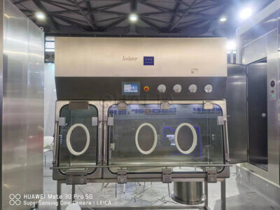
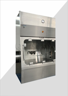
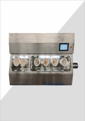
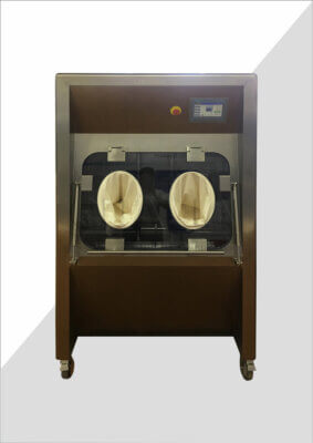
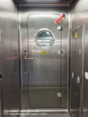
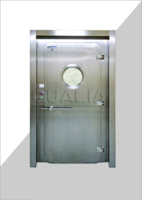
Comprender las compuertas de aislamiento de bioseguridad
Las compuertas de aislamiento de bioseguridad actúan como barreras críticas en entornos controlados en los que es necesario contener materiales o agentes patógenos peligrosos. A diferencia de las compuertas HVAC estándar, estos componentes especializados proporcionan capacidades de sellado hermético que evitan la contaminación cruzada entre espacios, protegiendo tanto al personal de laboratorio como a los entornos externos de la posible exposición a sustancias peligrosas.
Durante un reciente proyecto de puesta en marcha en una instalación de contención BSL-3, fui testigo de primera mano de cómo estos dispositivos mecánicos aparentemente sencillos forman la columna vertebral de un programa de bioseguridad eficaz. Su correcto funcionamiento no es una mera cuestión de comodidad o eficiencia energética, sino una defensa de primera línea contra fallos de contención potencialmente catastróficos.
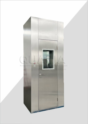
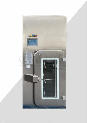
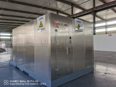
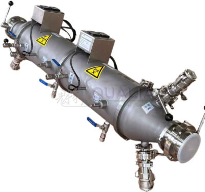
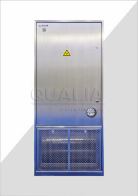
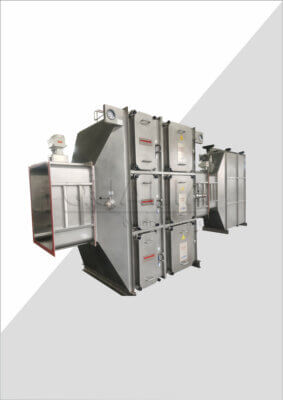
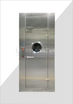
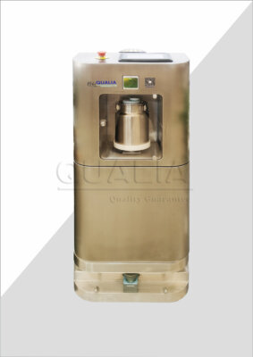
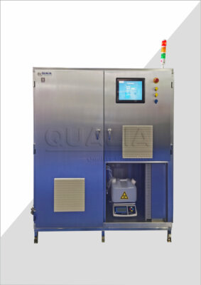
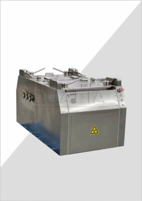
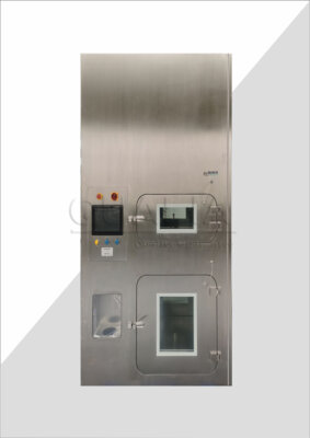
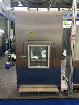
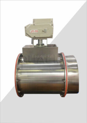
Los amortiguadores de aislamiento producidos por QUALIA destacan por su construcción robusta y su rendimiento fiable en aplicaciones exigentes. Lo que distingue a estos componentes es su capacidad de sellado hermético a las burbujas, que mantiene relaciones de presión críticas entre espacios adyacentes a la vez que garantiza cero fugas cuando están completamente cerrados.
Estos amortiguadores suelen constar de varios componentes clave:
- Un conjunto de bastidor que se monta dentro del conducto
- Hojas diseñadas con precisión que crean la barrera de flujo de aire real
- Juntas especializadas que garantizan un aislamiento completo cuando están cerradas
- Un sistema de actuadores que controla el posicionamiento de las palas
- Indicadores de posición y sistemas de retroalimentación que controlan el estado operativo
- Interfaces de control que se integran con los sistemas de automatización de edificios
Lo que hace que estos sistemas sean especialmente complejos es su integración con múltiples sistemas del edificio: controles de climatización, seguridad contra incendios, energía de emergencia y, a menudo, redes de supervisión de laboratorios. Esta interconexión significa que la resolución de problemas requiere no sólo conocimientos mecánicos, sino también una comprensión de la lógica de control y las dependencias del sistema.
Las especificaciones de las compuertas de bioseguridad de alta calidad revelan su complejidad técnica. Muchos modelos están diseñados para soportar presiones diferenciales superiores a 10″ WC (columna de agua), un requisito exigente que somete a los componentes a una tensión considerable con el paso del tiempo. El sitio web Compuerta de aislamiento de bioseguridad de QUALIA cuenta con diseños certificados por la AMCA que mantienen la integridad del rendimiento incluso en estas difíciles condiciones.
Con un mantenimiento adecuado, estas compuertas proporcionan años de servicio fiable. Sin embargo, su función crítica significa que incluso las averías menores requieren una atención inmediata y enfoques de solución de problemas adecuados.
Problemas comunes de las compuertas de bioseguridad y sus causas
Cuando se intentan solucionar problemas de compuertas de bioseguridad, es esencial comprender primero los modos de fallo más comunes. Tras más de una década trabajando con sistemas de contención críticos, he encontrado patrones de fallo que parecen repetirse en todas las instalaciones, independientemente del fabricante o el modelo.
Los fallos mecánicos representan quizás la categoría más sencilla de diagnosticar. Las lamas de las compuertas pueden atascarse físicamente debido a la acumulación de residuos, especialmente en entornos con partículas contaminantes. En una ocasión me encontré con una instalación en la que el material fibroso de los equipos de proceso se había acumulado gradualmente en los bordes de las lamas, impidiendo su cierre completo. Esto creó una situación peligrosa en la que la barrera de contención se vio comprometida a pesar de que los sistemas de control indicaban un funcionamiento correcto.
Los problemas de los actuadores constituyen otro problema mecánico común. Pueden manifestarse como:
| Tipo de emisión | Síntomas comunes | Posibles causas |
|---|---|---|
| Viajes incompletos | La compuerta no se abre/cierra completamente | Limitación del par del actuador, atasco en el varillaje |
| Movimiento errático | Posicionamiento incoherente | Engranajes dañados, problemas con las señales de control |
| Falta de respuesta | Sin movimiento a la señal de control | Pérdida de potencia, fallo del motor, varillaje roto |
| Respuesta lenta | Reacción retardada a las órdenes | Resistencia mecánica, alimentación inadecuada |
La conexión entre el actuador y las lamas de la compuerta representa otro posible punto de fallo. Con el tiempo, las conexiones mecánicas pueden aflojarse, creando holguras en el sistema que provocan un cierre incompleto o un posicionamiento errático. Esto es especialmente problemático en las compuertas de aislamiento, donde el cierre completo es fundamental para mantener unas relaciones de presión adecuadas.
Los problemas eléctricos presentan otra categoría de solución de problemas. Es posible que las señales de control no lleguen al actuador debido a fallos en el cableado, o que la propia tarjeta de control sufra un fallo. Moderno compuertas aislantes con funciones de control avanzadas a menudo incorporan sofisticados componentes electrónicos que, si bien proporcionan una mayor funcionalidad, también introducen posibles puntos de fallo adicionales.
La degradación de las juntas representa uno de los problemas más insidiosos, ya que puede producirse gradualmente y no ser inmediatamente evidente durante el funcionamiento rutinario. Los factores ambientales influyen enormemente en la longevidad de las juntas:
- La exposición química puede causar un deterioro prematuro
- Una humedad excesiva puede favorecer la proliferación de microbios en las superficies de sellado
- Las temperaturas extremas pueden provocar el endurecimiento o reblandecimiento del material
- La acumulación de partículas puede impedir el contacto adecuado de la junta
La Dra. Helena Ramírez, responsable de bioseguridad de una importante institución de investigación, subraya que "la integridad de los sellos no es sólo una cuestión mecánica, sino fundamentalmente de seguridad. Incluso las fugas microscópicas pueden permitir la transmisión de patógenos en entornos de alta contención".
Las irregularidades en el flujo de aire suelen indicar problemas subyacentes en las compuertas antes de que se produzca un fallo catastrófico. Las fluctuaciones inexplicables de la presión entre espacios, la dificultad para mantener los puntos de ajuste o los ruidos inusuales durante el funcionamiento pueden indicar la aparición de problemas con las compuertas de aislamiento. Lamentablemente, estos síntomas suelen atribuirse a otros componentes del sistema, lo que retrasa el diagnóstico y la reparación adecuados.
Los problemas de integración del sistema de control representan una categoría especialmente difícil para solucionar los problemas de las compuertas de bioseguridad. Cuando las compuertas no responden como se espera a las órdenes del sistema, el fallo puede estar en los propios componentes de la compuerta, en la señal de control o en la lógica que controla la secuencia de operaciones.
Precauciones de seguridad esenciales antes de solucionar problemas
Antes de intentar solucionar cualquier problema de compuertas en entornos de bioseguridad, los protocolos de seguridad deben tener prioridad absoluta. Aprendí esta lección al principio de mi carrera, cuando un ajuste aparentemente sencillo de una compuerta en un laboratorio de contención provocó una inversión temporal de la cascada de presión, una situación que podría haber tenido graves consecuencias si el espacio hubiera contenido agentes biológicos activos.
Para cualquier trabajo en los límites de contención críticos, como las compuertas de aislamiento, la selección del EPI adecuado no es negociable. Como mínimo, esto suele incluir:
- Guantes desechables adecuados para el entorno
- Bata o mono de laboratorio
- Protección ocular
- Protección respiratoria según el nivel de bioseguridad del laboratorio
- Pantalla facial para trabajos mecánicos en los que componentes accionados por resorte puedan soltarse inesperadamente
Más allá de los equipos de protección personal, la seguridad de los sistemas debe abordarse de forma sistemática. El Dr. William Chen, ingeniero de HVAC especializado en entornos críticos, subraya que "unos procedimientos adecuados de bloqueo y etiquetado son especialmente cruciales cuando se trabaja con sistemas de aislamiento. No sólo se evitan daños en los equipos, sino que se mantiene la integridad de la contención que protege tanto al personal como al medio ambiente".
Antes de iniciar cualquier trabajo de localización de averías, debe documentarse una evaluación formal de riesgos:
- Estado actual de contención del espacio afectado
- Posibles consecuencias de la manipulación del sistema
- Medidas de seguridad y EPI necesarios
- Protocolos de comunicación con el personal del laboratorio
- Planes de contingencia para respuestas inesperadas del sistema
La especialista en certificación de laboratorios Eliza Thornton señala que "la documentación antes, durante y después de la resolución de problemas no es mero papeleo burocrático: crea un registro crítico del estado del sistema que puede identificar patrones de fallo y prevenir futuros incidentes".
Cuando me dispongo a solucionar problemas de compuertas de bioseguridad, siempre verifico si el espacio afectado puede descontaminarse de forma segura antes de empezar a trabajar. En muchos casos, esto significa programar el mantenimiento durante el tiempo de inactividad previsto del laboratorio, cuando los espacios se han sometido a los procedimientos de descontaminación adecuados.
Para reparaciones de emergencia en espacios de contención activos, se hacen necesarios protocolos adicionales:
| Nivel de bioseguridad | Requisitos previos al trabajo | Restricciones de personal | Verificación posterior a los trabajos |
|---|---|---|---|
| BSL-1 | Protocolos de seguridad HVAC estándar | Restricciones mínimas | Sólo pruebas funcionales |
| BSL-2 | Descontaminación espacial recomendada | Limitado al personal esencial | Inspección visual y comprobación del equilibrio del aire |
| BSL-3 | Se requiere descontaminación completa | Se necesita la aprobación del responsable de bioseguridad | Verificación completa de la presión y prueba de humos |
| BSL-4 | Protocolos completos de desconexión | Equipo especializado con formación específica | Se requiere una recertificación exhaustiva |
Otra consideración de seguridad fundamental es conocer las posiciones de seguridad del sistema. A diferencia de las compuertas HVAC convencionales, que pueden fallar en posiciones abiertas o cerradas por motivos de eficiencia energética, las compuertas de aislamiento de bioseguridad suelen emplear posiciones de seguridad específicas dictadas por los requisitos de contención. Estos requisitos deben conocerse a fondo antes de iniciar la localización de averías para evitar brechas involuntarias en la contención.
Proceso de diagnóstico paso a paso de las compuertas de bioseguridad
Desarrollar un enfoque sistemático para solucionar los problemas de las compuertas de bioseguridad es esencial para realizar un diagnóstico eficaz y mantener la seguridad. Tras años de experiencia sobre el terreno, he perfeccionado un proceso de diagnóstico que identifica los problemas al tiempo que minimiza la interrupción del sistema.
Comience por recopilar información antes de la inspección física. Esto crea un contexto para la resolución de problemas:
- Revisar el sistema de automatización del edificio (BAS) en busca de datos históricos de rendimiento.
- Entrevistar al personal del laboratorio sobre los síntomas observados
- Compruebe los registros de mantenimiento en busca de problemas o reparaciones anteriores
- Verifique los puntos de ajuste actuales del sistema y los parámetros de funcionamiento
- Comprender la secuencia de funcionamiento normal de la compuerta
Con esta base, proceda a la inspección visual del compuerta de aislamiento de bioseguridad. Este paso suele revelar problemas sorprendentes que, de otro modo, podrían pasarse por alto. Una vez descubrí una avería en una compuerta causada por una bolsa de plástico de laboratorio que se había introducido en el sistema, algo que nunca se habría diagnosticado únicamente a partir de las señales de control.
Durante la inspección visual, compruebe sistemáticamente:
- Posición física de la hoja frente a la posición indicada
- Compruebe si las conexiones del varillaje están sueltas o atascadas
- Seguridad de montaje del actuador
- Signos de corrosión o daños físicos
- Evidencia de humedad o contaminación en los componentes
- Estado de la junta y uniformidad del contacto
- Integridad del marco de montaje
Para verificar las señales de control, es esencial disponer del equipo de pruebas adecuado. Un multímetro con capacidades de medición de tensión y resistencia es el requisito mínimo, pero los problemas más complejos pueden requerir herramientas especializadas:
| Herramienta de diagnóstico | Aplicable a | Información facilitada |
|---|---|---|
| Multímetro | Resolución de problemas eléctricos básicos | Presencia de tensión, intensidad de la señal, continuidad |
| Manómetro de presión diferencial | Verificación del flujo de aire | Relaciones de presión real, eficacia del sellado |
| Lápiz de humo | Detección de fugas | Confirmación visual de la dirección del movimiento del aire |
| Generador de señales de control | Pruebas de actuadores | Verificación independiente de la respuesta de los amortiguadores |
| Cámara termográfica | Análisis de motores y rodamientos | Puntos calientes que indican una fricción excesiva o problemas eléctricos |
Al probar la respuesta del actuador, he encontrado un enfoque metódico funciona mejor. Comience por desconectar la señal de control y la aplicación de tensión directa (dentro de las especificaciones) para verificar el actuador funciona independientemente del sistema de control. Esto aísla si los problemas se originan en el conjunto mecánico o los componentes de control.
Para las compuertas con actuadores neumáticos, James Wilson, un especialista en puesta en servicio con el que he colaborado, recomienda comprobar primero la presión de la línea de aire: "Los sistemas neumáticos suelen desarrollar pequeñas fugas con el tiempo que crean una caída de presión suficiente para reducir la fuerza del actuador por debajo de lo necesario para un funcionamiento correcto, especialmente con conjuntos de compuertas más grandes."
El mecanismo de retroalimentación de posición representa otro posible punto de fallo. Los sistemas de control modernos dependen de datos de posición precisos, y los potenciómetros o interruptores de posición defectuosos pueden crear bucles de control en los que el sistema intenta ajustar continuamente una compuerta que ya está en la posición correcta, lo que provoca un desgaste prematuro de los componentes.
Para usuarios avanzados con el equipo adecuado, la medición del consumo de corriente del actuador durante el funcionamiento puede revelar un atasco mecánico antes de que cause un fallo completo. Los picos de corriente durante ciertos tramos del recorrido suelen indicar el desarrollo de una resistencia mecánica que debe tratarse de forma preventiva.
Cuando una compuerta de aislamiento de bioseguridad muestra una respuesta adecuada a los comandos manuales, pero una respuesta inadecuada a los comandos del sistema, es probable que el problema resida en la lógica de control o en la transmisión de la señal. En estos casos, trace sistemáticamente la ruta de la señal desde el controlador hasta el actuador, comprobando las conexiones y la integridad de la señal en cada punto de unión.
El proceso de diagnóstico debe concluir siempre con pruebas funcionales exhaustivas que verifiquen tanto el funcionamiento mecánico como la integración del sistema: una compuerta que funcione correctamente no sólo debe moverse correctamente, sino que debe hacerlo en los momentos adecuados y en coordinación con los sistemas relacionados.
Soluciones rápidas para problemas mecánicos y de actuadores
Una vez identificados los problemas mecánicos mediante protocolos de diagnóstico adecuados, la aplicación de soluciones eficaces requiere conocimientos técnicos y herramientas apropiadas. Gracias a mi experiencia en la resolución de problemas de compuertas de bioseguridad en entornos críticos, he desarrollado varias soluciones para problemas mecánicos comunes que a menudo pueden aplicarse sin necesidad de sustituir todo el sistema.
El agarrotamiento de las lamas es uno de los problemas mecánicos más frecuentes. Cuando las lamas del amortiguador no se mueven libremente en toda su amplitud de movimiento, se pueden adoptar varias medidas:
Limpieza cuidadosa de los bordes de las cuchillas y las juntas: Con alcohol isopropílico o un limpiador adecuado que no deje residuos, limpie a fondo los bordes de las cuchillas para eliminar las partículas acumuladas o los residuos pegajosos. Asegúrese de utilizar materiales sin pelusa que no dejen fibras.
Inspección y ajuste de la alineación de las cuchillas: La alineación de precisión de las cuchillas en compuertas aislantes de alta calidad a veces pueden desplazarse debido a tensiones de montaje o impactos físicos. Utilizando galgas de espesores, verifique que las holguras sean uniformes y ajústelas según sea necesario.
Lubricación de rodamientos: Aplique un lubricante adecuado a los cojinetes de las palas, teniendo cuidado de utilizar productos compatibles con el entorno. Para entornos de laboratorio, prefiero lubricantes a base de silicona que no atraigan el polvo y mantengan sus propiedades en todos los rangos de temperatura.
Los problemas de los actuadores suelen clasificarse en varias categorías que a menudo pueden solucionarse sin necesidad de sustituirlos por completo:
| Edición | Solución rápida | Herramientas necesarias |
|---|---|---|
| Par limitado | Recalibrado del actuador, refuerzo del soporte | Llave dinamométrica, tornillería de montaje |
| Movimiento errático | Limpieza de señales de control, verificación de tierra | Limpiador de contactos eléctricos, multímetro |
| Actuador no reactivo | Reinicio de la tarjeta de control, ciclo de alimentación | Herramientas aisladas, fuente de tensión de prueba |
| Movimiento incompleto | Ajuste del límite de recorrido, reconfiguración del elevador | Herramientas de calibración específicas de la marca del actuador |
Para los actuadores eléctricos con controles de microprocesador, la realización de un restablecimiento de fábrica a menudo resuelve el comportamiento errático. Esto normalmente implica una secuencia específica de ciclos de energía o pulsaciones de botones detallados en la documentación del fabricante. Mantengo una biblioteca de estos procedimientos en mi tableta para referencia en el campo.
Los ajustes del varillaje requieren una especial atención a los detalles. La conexión entre el actuador y las lamas de la compuerta debe transferir el movimiento con precisión y, al mismo tiempo, adaptarse al arco de rotación de los componentes. Al solucionar problemas de conexión de compuertas de bioseguridad:
- Compruebe que los herrajes de conexión están apretados pero no atascados.
- Asegúrese de que las bielas o las varillas de empuje no estén dobladas.
- Comprobar que los puntos de fijación no presentan un desgaste excesivo.
- Confirmar que el movimiento es suave en todo el recorrido
Un problema recurrente con el que me he encontrado son las abrazaderas de eje que se deslizan gradualmente con el tiempo, creando una desconexión entre el movimiento del actuador y la posición de la hoja. Marcar el eje y la abrazadera con indicadores de alineación utilizando un rotulador permanente proporciona una referencia visual rápida para comprobar este problema común durante el mantenimiento futuro.
En el caso de amortiguadores que hayan desarrollado una fricción excesiva debido a las condiciones ambientales, puede ser necesario desmontar y limpiar cuidadosamente los componentes. Esto sólo debe intentarse en entornos totalmente descontaminados y con los protocolos de seguridad adecuados. Un ingeniero de puesta en servicio con el que trabajé desarrolló un método inteligente utilizando lubricante seco de calidad alimentaria aplicado a las juntas de los bordes de las palas que redujo significativamente la fricción sin comprometer la eficacia del sellado.
Cuando se trabaja con actuadores neumáticos, la calidad del suministro de aire suele ser el problema subyacente. La instalación de pequeños filtros en línea justo antes del actuador puede evitar que la contaminación llegue a los componentes sensibles. Estos filtros pueden instalarse a posteriori incluso en sistemas que no los incluían originalmente.
Durante una sesión de resolución de problemas de compuertas de bioseguridad especialmente complicada en una instalación farmacéutica, descubrimos que los diferenciales de presión extrema superaban el par nominal del actuador. La solución consistió en instalar un pequeño bypass de alivio de presión que limitaba la presión diferencial máxima sin comprometer la contención, un equilibrio de consideraciones de ingeniería que mantenía la integridad del sistema al tiempo que permitía un funcionamiento correcto.
Recuerde que las reparaciones mecánicas siempre deben ir seguidas de pruebas exhaustivas para verificar tanto el correcto funcionamiento mecánico como la correcta integración del sistema. Esto incluye la comprobación del cierre completo, la compresión adecuada de la junta y la verificación de los indicadores de posición en todo el rango de recorrido.
Resolución de problemas de control eléctrico
Los problemas eléctricos de las compuertas de aislamiento de bioseguridad suelen presentar dificultades de diagnóstico más sutiles que los problemas mecánicos. Estos componentes críticos suelen incorporar sofisticados sistemas de control que interactúan con las redes de automatización de edificios, lo que presenta múltiples puntos potenciales de fallo. Según mi experiencia en la resolución de problemas, abordar los problemas eléctricos de forma sistemática da los mejores resultados.
Empiece por lo básico: verificación de la alimentación. Este paso aparentemente obvio se pasa por alto con frecuencia, sin embargo, he resuelto numerosas llamadas de servicio simplemente confirmando la tensión adecuada en el actuador. En los sistemas de 24 V que se utilizan habitualmente con compuertas de aislamiento, la caída de tensión en los tramos largos de cable puede reducir la potencia disponible por debajo de los umbrales operativos, especialmente en aplicaciones de par elevado. La medición de la tensión tanto en la salida del controlador como en los terminales del actuador puede identificar rápidamente este problema.
La integridad del cableado representa el siguiente punto de verificación. Los factores ambientales de los laboratorios (humedad, productos químicos de limpieza y, en ocasiones, vibraciones) pueden acelerar el deterioro de los conductores. Realice una inspección visual de todo el cableado accesible, buscando:
- Decoloración que indica sobrecalentamiento
- Aislamiento quebradizo o agrietado
- Corrosión en las conexiones de los terminales
- Tensión en los puntos de conexión
- Evidencia de daños por roedores (especialmente en los espacios del techo)
En el caso de problemas eléctricos intermitentes que han sido difíciles de solucionar eficazmente, he tenido éxito con una metódica "prueba de meneo": flexionar cuidadosamente los mazos de cables mientras el sistema funciona para identificar conexiones sueltas. Este enfoque práctico a menudo revela problemas que los equipos de prueba sofisticados pasan por alto.
La calidad de la señal de control merece especial atención. Los amortiguadores de aislamiento modernos pueden utilizar varios enfoques de control diferentes:
| Tipo de control | Problemas comunes | Técnica de verificación |
|---|---|---|
| 0-10V CC | Bucles de tierra, degradación de la señal | Medir la tensión con el sistema en diferentes posiciones |
| 4-20 mA | Circuitos abiertos, desajustes de impedancia | Verificar el flujo de corriente con el calibrador de bucle |
| Flotante/Triestado | Problemas de sincronización, comandos atascados | Probar componentes de circuito individuales con tensión directa |
| En red (BACnet, Modbus) | Errores de comunicación, resolución de problemas | Utilizar analizadores específicos de protocolo para verificar los paquetes de datos |
En la resolución de problemas de sistemas de control en red, los errores de configuración suelen hacerse pasar por fallos de hardware. Un caso especialmente complicado que me encontré fue el de una compuerta que funcionaba correctamente cuando se le ordenaba manualmente, pero que no respondía a las órdenes de automatización. Tras numerosas pruebas, descubrimos que una actualización reciente de la red había cambiado el número de instancia del dispositivo, lo que hacía que los comandos se enviaran al dispositivo equivocado.
Los procedimientos de restablecimiento del controlador varían según el fabricante, pero a menudo pueden resolver problemas relacionados con el firmware. Para el compuertas aislantes de alto rendimiento con controles inteligentesUna secuencia de restablecimiento documentada puede eliminar fallos sin necesidad de sustituir componentes. Documente siempre la configuración existente antes de realizar reinicios, ya que los ajustes pueden volver a los valores predeterminados de fábrica.
La interferencia de señales presenta otra categoría difícil de diagnosticar. En entornos de laboratorio con numerosos equipos electrónicos, las interferencias electromagnéticas pueden alterar las señales de control. Los cables apantallados ofrecen la mejor protección, pero las instalaciones existentes pueden requerir soluciones de adaptación:
- Núcleos de ferrita instalados en el cableado de control cerca del actuador
- Separación del cableado de control del cableado de alimentación
- Conductos específicos para señales de control sensibles
- Conexión a tierra adecuada de todos los componentes del sistema
Para los actuadores con mecanismos de retroalimentación de posición, los errores de calibración pueden crear información de diagnóstico engañosa. Cuando los indicadores de posición no coinciden con la observación física, puede ser necesario recalibrar. Esto suele implicar colocar la compuerta en posición totalmente cerrada y restablecer el punto de referencia de posición, repitiendo a continuación para la posición totalmente abierta.
Las consideraciones sobre la sustitución deben incluir la verificación de la compatibilidad. Los actuadores más nuevos pueden ofrecer una funcionalidad mejorada, pero podrían requerir modificaciones en el sistema de control para lograr una integración adecuada. A la hora de seleccionar componentes de recambio, doy prioridad a los recambios directos del fabricante original siempre que sea posible, ya que suelen minimizar los problemas de integración.
Recuerde que la resolución de problemas eléctricos en entornos de laboratorio requiere consideraciones de seguridad adicionales debido a la presencia de sustancias potencialmente conductoras o corrosivas. Utilice siempre equipos de prueba con la clasificación adecuada y siga los protocolos de seguridad eléctrica apropiados.
Afrontar los retos del flujo de aire y la estanqueidad
El objetivo último de las compuertas de aislamiento de bioseguridad es mantener las relaciones de presión críticas y evitar la contaminación cruzada, por lo que los problemas de flujo de aire y sellado son especialmente preocupantes. Estos problemas requieren un enfoque diferente al de la resolución de problemas puramente mecánicos o eléctricos, centrándose en la dinámica del sistema y la integridad de la contención.
La integridad de las juntas es la base del buen funcionamiento de las compuertas de aislamiento. A lo largo de los años de experiencia sobre el terreno, he comprobado que la degradación de las juntas suele producirse gradualmente, lo que dificulta su detección mediante la observación casual. Un proceso de inspección sistemático incluye:
- Examen visual para detectar daños físicos o deformaciones
- Pruebas de compresión con galgas de espesores o herramientas similares
- Evaluación de la flexibilidad de los materiales elastoméricos
- Verificación de los patrones de contacto adecuados cuando está completamente cerrado
Los factores ambientales influyen considerablemente en la longevidad de las juntas. Las exposiciones químicas habituales en los entornos de laboratorio pueden acelerar el deterioro, mientras que las temperaturas extremas pueden modificar las propiedades de los materiales. Durante un proyecto de solución de problemas de compuertas de bioseguridad en una planta de fabricación farmacéutica, descubrimos que los procedimientos periódicos de limpieza con vapor estaban degradando las juntas de silicona, por lo que fue necesario cambiar a un material más resistente a los productos químicos.
Para solucionar los problemas de estanquidad sin una sustitución completa, existen varios métodos provisionales que pueden restablecer la funcionalidad:
- Limpieza cuidadosa de las superficies de sellado con disolventes apropiados no dañinos
- Aplicación de silicona homologada o lubricantes similares para reducir la fricción y mejorar la estanqueidad.
- Ajuste de las posiciones de los topes de las cuchillas para aumentar la compresión de la junta
- Instalación de materiales de sellado suplementarios cuando el diseño lo permita
Las pruebas cuantitativas de estanqueidad proporcionan datos objetivos sobre la eficacia del sellado. Aunque existen equipos de ensayo sofisticados, los métodos prácticos de campo pueden arrojar resultados útiles:
| Método de ensayo | Equipo necesario | Escenario de aplicación |
|---|---|---|
| Prueba de caída de presión | Manómetro calibrado, método para aislar la sección | Sistema con capacidad para aislar secciones de conductos |
| Visualización del lápiz de humo | Generador de humo químico | Confirmación visual de la localización de fugas |
| Detección de fugas por ultrasonidos | Detector ultrasónico con la gama de frecuencias adecuada | Pruebas no invasivas de sistemas ensamblados |
| Análisis diferencial de presión | Manómetro de precisión | Comparación de las relaciones de presión previstas frente a las reales |
Al solucionar problemas de flujo de aire que implican amortiguadores de aislamiento que funcionan correctamenteSin embargo, a menudo el problema radica en el equilibrio del sistema y no en la compuerta en sí. Thomas Reynolds, especialista en calefacción, ventilación y aire acondicionado con el que he colaborado en varios proyectos, señala que "las compuertas son solo un componente de un complejo sistema de presión en cascada; una puesta en servicio adecuada requiere examinar todo el recorrido del flujo de aire, no solo los componentes individuales."
Para los sistemas que experimentan dificultades para mantener los diferenciales de presión establecidos, considere estos factores:
- Verificación del funcionamiento de los ventiladores de impulsión y extracción
- Evaluación del estado de carga del filtro
- Evaluación de las demandas de flujo de aire de los espacios adyacentes
- Examen de factores ambientales como la carga del viento en los sistemas de escape exteriores
La Dra. Sarah Jameson, investigadora biomolecular, subraya la importancia biológica de un sellado adecuado: "Incluso las fugas microscópicas en las barreras de aislamiento pueden permitir la transmisión de patógenos. Hemos documentado partículas viables moviéndose a través de huecos tan pequeños como 3 micras en entornos de laboratorio."
Para restablecer temporalmente la estanquidad mientras se esperan las piezas de recambio, los sellantes de silicona de calidad alimentaria compatibles con entornos de laboratorio pueden ofrecer una solución provisional para las juntas estáticas (aunque nunca para los componentes móviles). He utilizado con éxito este método en situaciones de emergencia, pero nunca debe considerarse una solución permanente.
Cuando las relaciones de presión entre espacios fluctúan a pesar de unas compuertas aparentemente funcionales, el problema suele estar relacionado con la sincronización y la secuencia del sistema de control. Los laboratorios modernos suelen emplear complejas estrategias de control en cascada que pueden generar conflictos entre demandas contrapuestas. La revisión de las secuencias de control y el ajuste de los parámetros de temporización pueden resolver estas sutiles interacciones sin cambios en el hardware.
Recuerde que la verificación del rendimiento del flujo de aire debe seguir siempre a cualquier actividad de mantenimiento o sustitución de los precintos. Esto incluye no sólo el funcionamiento funcional, sino también la verificación de los parámetros de contención adecuados al nivel de bioseguridad de la instalación.
Herramientas y técnicas avanzadas de diagnóstico
A medida que los sistemas de compuertas de aislamiento de bioseguridad han evolucionado en complejidad, también lo han hecho las herramientas y técnicas para diagnosticar problemas. Más allá de los multímetros y manómetros básicos, los métodos de diagnóstico avanzados pueden identificar problemas sutiles antes de que se conviertan en fallos críticos, sobre todo en entornos de alta contención donde la integridad del sistema es primordial.
El mapeo digital de la presión representa un avance significativo en el diagnóstico del flujo de aire. Mediante el uso de varios sensores de presión conectados en red y colocados por todo el sistema de ventilación, los técnicos pueden crear una visualización en tiempo real de las cascadas de presión. Este enfoque revela relaciones dinámicas que las mediciones puntuales podrían pasar por alto, sobre todo al solucionar problemas de compuertas de bioseguridad relacionados con interacciones del sistema en lugar de fallos de componentes individuales.
Las cámaras termográficas han adquirido un valor incalculable para identificar problemas mecánicos que generan fricción por calor, mecanismos de unión o problemas de resistencia eléctrica; todos ellos producen firmas térmicas detectables antes de que se produzca un fallo catastrófico. Durante una reciente sesión de diagnóstico en un laboratorio de contención, identifiqué un fallo inminente del actuador mediante un análisis térmico a pesar de que la compuerta parecía funcionar con normalidad durante las pruebas estándar.
Entre los equipos especializados para determinados retos de diagnóstico se incluyen:
| Herramienta de diagnóstico | Aplicación | Ventajas sobre los métodos tradicionales |
|---|---|---|
| Detectores de fugas por ultrasonidos | Pruebas de estanquidad no destructivas | Puede identificar fugas demasiado pequeñas para las pruebas con humo mientras el sistema sigue funcionando |
| Analizadores de calidad eléctrica | Resolución de problemas de los sistemas de control | Identifica las anomalías de tensión que afectan a los componentes controlados por microprocesador. |
| Analizadores de protocolos de red | Problemas de integración de BAS | Captura paquetes de datos reales para verificar la integridad de la comunicación |
| Contadores de partículas | Verificación de la contención | Proporciona una medición cuantitativa de la eficacia de la contención |
El software de diagnóstico específico del fabricante es cada vez más valioso, sobre todo para los sistemas de amortiguadores sofisticados con controles integrados. Muchos sitios sistemas modernos de amortiguadores de aislamiento incluyen diagnósticos a bordo accesibles a través de interfaces patentadas, que proporcionan datos operativos detallados no disponibles a través de los sistemas estándar de automatización de edificios. Para mí es esencial mantener relaciones con los representantes de los fabricantes para acceder a estas herramientas cuando sea necesario.
El análisis de tendencias de datos ha revolucionado los métodos de resolución de problemas. Al examinar los patrones de rendimiento a lo largo del tiempo en lugar de mediciones puntuales, se hace evidente una degradación sutil antes de que se produzca un fallo completo. Elena Rodríguez, especialista en automatización de laboratorios, explica: "La capacidad de analizar los tiempos de respuesta de las compuertas a lo largo de meses revela tendencias invisibles para las pruebas tradicionales: ahora podemos predecir fallos semanas antes de que afecten a las operaciones."
Las capacidades de monitorización remota permiten la observación continua del sistema sin interrumpir las operaciones del laboratorio. Para aplicaciones especialmente sensibles, he implantado sistemas de supervisión que realizan un seguimiento continuo de parámetros críticos, almacenan datos para su análisis y emiten alertas cuando el rendimiento se desvía de los parámetros establecidos.
El modelado 3D y la dinámica de fluidos computacional (CFD) han ganado adeptos en la resolución de problemas complejos. Mediante la creación de modelos digitales de los sistemas de distribución de aire, los ingenieros pueden simular diferentes condiciones de funcionamiento e identificar posibles problemas antes de implementar cambios físicos. Aunque requiere conocimientos especializados, este enfoque resulta especialmente valioso cuando los métodos de diagnóstico tradicionales arrojan resultados incoherentes.
En el caso de instalaciones con varios amortiguadores idénticos, el análisis comparativo del rendimiento puede identificar valores atípicos que merecen una inspección más minuciosa. Al establecer líneas de base de rendimiento entre componentes similares, se ponen de manifiesto variaciones sutiles que, de otro modo, podrían pasar desapercibidas al examinar los componentes individualmente.
Cuando los enfoques estándar no consiguen resolver los problemas persistentes, el modelado de laboratorio mediante la visualización de humo o aerosoles puede revelar patrones de flujo de aire invisibles para otros métodos de ensayo. Este enfoque requiere una planificación cuidadosa y protocolos de seguridad adecuados, pero proporciona una visión sin precedentes del comportamiento real del flujo de aire dentro de los entornos de contención.
Recuerde que los métodos de diagnóstico avanzados complementan, más que sustituyen, los conocimientos básicos de localización de averías. Las herramientas más sofisticadas siguen requiriendo una interpretación adecuada basada en la comprensión del sistema y los principios mecánicos.
Mantenimiento preventivo para evitar problemas futuros
Invertir en el mantenimiento proactivo de las compuertas de aislamiento de bioseguridad ofrece beneficios significativos: evita costosas reparaciones de emergencia, evita el tiempo de inactividad del laboratorio y, lo que es más importante, mantiene la integridad de la contención. Mi experiencia en la gestión de infraestructuras de entornos críticos ha demostrado que los enfoques preventivos sistemáticos reducen drásticamente los fallos inesperados.
El desarrollo de un programa de mantenimiento exhaustivo específico para las compuertas de aislamiento requiere equilibrar factores contrapuestos: frecuencia de inspección, interrupción del funcionamiento y asignación de recursos. Aunque no existe un programa universal, estas directrices proporcionan un marco de partida:
| Componente | Frecuencia de inspección | Acciones de mantenimiento | Señales de advertencia |
|---|---|---|---|
| Juntas de las cuchillas | Trimestral | Limpiar, inspeccionar el desgaste, lubricar si procede | Deformación visible, endurecimiento, agrietamiento |
| Actuador | Semestralmente | Comprobar montaje, limpiar, verificar recorrido completo | Ruido inusual, posicionamiento incoherente, respuesta lenta |
| Enlace | Trimestral | Inspeccionar el desgaste, apretar las conexiones, lubricar | Juego visible en las conexiones, agarrotamiento durante el funcionamiento |
| Interruptores de posición | Anualmente | Verificar la precisión, limpiar los contactos | Notificación de posición errática, funcionamiento intermitente |
| Conexiones de control | Semestralmente | Comprobar la corrosión, verificar la seguridad | Respuesta intermitente a los comandos, mensajes de error |
Las pruebas de verificación del rendimiento deben ir más allá de las simples comprobaciones operativas. Para compuertas aislantes de bioseguridad que protegen entornos críticosEn las pruebas de funcionamiento se debe verificar la integridad de la contención en diversas condiciones. El ingeniero de HVAC Michael Thornton recomienda: "Desafíe al sistema simulando diferentes estados operativos: fallos de alimentación, aperturas de puertas adyacentes y volúmenes de aire de suministro variables. Los sistemas de contención deben mantener la integridad en todos los escenarios razonables".
Las prácticas de documentación influyen considerablemente en la eficacia del mantenimiento. Además de registrar las fechas de finalización, la documentación completa debe incluir:
- Mediciones reales de parámetros clave (requisitos de par, tiempos de cierre, compresión de la junta)
- Condiciones observadas que requieren supervisión pero no corrección inmediata
- Correlación con actividades de laboratorio que puedan afectar al rendimiento
- Comparación con los valores de referencia establecidos durante la puesta en servicio
- Fotos de los componentes que muestren los cambios de estado a lo largo del tiempo
Este nivel de detalle facilita el análisis de tendencias que puede identificar problemas en desarrollo antes de que causen problemas operativos. Durante una revisión de mantenimiento preventivo, nuestro equipo observó un aumento gradual del consumo de corriente del actuador a lo largo de varias inspecciones, un indicador precoz del aumento de la resistencia mecánica que abordamos antes de que se produjera el fallo.
La formación adecuada del personal de mantenimiento representa otra medida preventiva crucial. Los sistemas de contención de los laboratorios difieren significativamente de los equipos comerciales de calefacción, ventilación y aire acondicionado, y requieren conocimientos especializados. He comprobado que la formación cruzada entre el personal de mantenimiento mecánico y el personal de seguridad de los laboratorios genera un valioso intercambio de conocimientos: los técnicos de mantenimiento adquieren mayor conocimiento de las implicaciones de la contención, mientras que el personal de laboratorio comprende mejor las limitaciones mecánicas.
Un aspecto del mantenimiento preventivo que a menudo se pasa por alto es la gestión de las piezas de repuesto. Es preciso identificar, inventariar y almacenar in situ los componentes de repuesto críticos, sobre todo si se trata de artículos especializados con plazos de entrega largos. Esta preparación puede transformar una posible parada de laboratorio de una semana en una reparación en el mismo día.
La vigilancia ambiental en torno a las instalaciones de amortiguadores ofrece otro enfoque preventivo. Los sensores de temperatura, humedad e incluso vibración colocados cerca de las compuertas críticas pueden identificar condiciones cambiantes que podrían acelerar el deterioro de los componentes. Este enfoque basado en datos permite intervenir antes de que los factores ambientales provoquen fallos.
Cuando la solución de problemas de compuertas de bioseguridad revele problemas sistémicos, considere la posibilidad de aplicar mejoras de diseño durante el mantenimiento programado. Por ejemplo, tras detectar problemas recurrentes de condensación que afectaban a los componentes electrónicos de los actuadores, instalamos armarios protectores que prolongaron considerablemente la vida útil de los componentes sin necesidad de sustituir todo el sistema.
Por último, la recertificación periódica por parte de profesionales cualificados garantiza que el mantenimiento preventivo alcance su objetivo previsto de fiabilidad del sistema. La verificación por terceros proporciona una evaluación objetiva de la integridad del confinamiento que complementa los programas de mantenimiento internos.
En última instancia, un mantenimiento preventivo eficaz requiere un compromiso con los procesos sistemáticos en lugar de respuestas reactivas. La inversión resulta rentable gracias a la prolongación de la vida útil del sistema, la reducción de las reparaciones de emergencia y, lo que es más importante, la integridad constante del confinamiento para la seguridad del personal de laboratorio.
Conclusiones y buenas prácticas
A través de esta exploración de la resolución de problemas de compuertas de aislamiento de bioseguridad, surgen varios principios clave que trascienden a fabricantes o aplicaciones específicos. Estos componentes críticos exigen enfoques sistemáticos que equilibren los conocimientos técnicos con la conciencia de la seguridad.
El proceso de diagnóstico debe seguir siempre una progresión lógica de lo general a lo específico, comenzando por comprender la intención del diseño del sistema, pasando por la observación no invasiva y, sólo entonces, aplicando la resolución práctica de problemas. Este enfoque metódico minimiza las interrupciones innecesarias del sistema y maximiza la eficacia del diagnóstico.
A la hora de aplicar soluciones, mantener una documentación adecuada crea un valioso conocimiento institucional que sirve para futuros esfuerzos de mantenimiento. Más allá de dejar constancia de lo que se ha hecho, documentar por qué se han elegido determinados enfoques proporciona un contexto que ayuda a los futuros técnicos a tomar decisiones informadas cuando surjan problemas similares.
La comunicación entre el personal técnico y el de laboratorio resulta esencial para la resolución eficaz de los problemas. Los usuarios de laboratorio suelen notar cambios sutiles en el rendimiento del sistema: ligeras diferencias de presión, anomalías inusuales, etc.
Preguntas frecuentes de Solución de problemas de la compuerta de bioseguridad
Q: ¿Cómo identifico los problemas de mi compuerta de bioseguridad?
R: La identificación de problemas en su compuerta de bioseguridad implica la observación de signos de mal funcionamiento, como ruidos inusuales, flujo de aire inadecuado o señales de alarma. Las comprobaciones periódicas de mantenimiento pueden ayudar a detectar problemas a tiempo, garantizando el funcionamiento continuo de la compuerta.
Q: ¿Cuáles son las causas más comunes de mal funcionamiento de las compuertas de bioseguridad?
R: Entre las causas más comunes de mal funcionamiento de las compuertas de bioseguridad se encuentran los filtros de aire obstruidos, una instalación incorrecta u obstrucciones físicas en la trayectoria del flujo de aire. Solucionar estos problemas con prontitud puede evitar problemas más graves y garantizar un funcionamiento seguro.
Q: ¿Cómo puedo solucionar los problemas de flujo de aire en mi compuerta de bioseguridad?
R: Para solucionar los problemas de flujo de aire, compruebe si hay obstrucciones en las vías de aire, asegúrese de que los filtros están limpios o se han sustituido y ajuste la regulación de la compuerta si es necesario. Utilice un velómetro para medir la velocidad del aire, que debe coincidir con las especificaciones del fabricante.
Q: ¿Qué precauciones de seguridad debo tomar para solucionar los problemas de una compuerta de bioseguridad?
R: Cuando solucione un problema con una compuerta de bioseguridad, lleve siempre el equipo de protección individual (EPI) adecuado, evite trabajar con materiales de riesgo biológico hasta que se resuelva el problema y siga los protocolos de seguridad establecidos para minimizar los riesgos de exposición.
Q: ¿Puedo solucionar yo mismo los problemas de una compuerta de bioseguridad o necesito ayuda profesional?
R: Las tareas básicas de solución de problemas, como la limpieza o la comprobación de obstrucciones, puede realizarlas usted mismo. Sin embargo, los problemas complejos pueden requerir la asistencia de un profesional certificado para garantizar el cumplimiento de las normas de seguridad y un rendimiento óptimo.
Q: ¿Con qué frecuencia debo realizar el mantenimiento rutinario de mi compuerta de bioseguridad?
R: El mantenimiento regular debe realizarse anual o semestralmente para garantizar un funcionamiento óptimo. Esto incluye la comprobación de la velocidad del aire, la limpieza de los filtros y la inspección de cualquier signo de desgaste o daño.
Recursos externos
Lamentablemente, no pude encontrar ningún recurso que coincidiera directamente con la palabra clave "Solucionar problemas de compuertas de bioseguridad". Por lo tanto, voy a enumerar los recursos estrechamente relacionados que pueden ser útiles para la solución de problemas gabinetes de bioseguridad o amortiguadores:
Procedimiento de respuesta ante un fallo de la cabina de seguridad biológica - Este recurso proporciona pasos para responder a los fallos de las cabinas de seguridad biológica, que pueden ser útiles a la hora de solucionar problemas relacionados con las compuertas de seguridad biológica.
Manual del usuario del armario de bioseguridad de clase II, tipo A2 - Ofrece directrices detalladas para el usuario de cabinas de bioseguridad, incluida información para la resolución de problemas que podría ayudar indirectamente con los problemas de las compuertas.
Manual de cabinas de bioseguridad Purifier Axiom Clase II C1 - Proporciona orientación sobre la instalación y el funcionamiento de las cabinas de bioseguridad, incluidos los ajustes de las compuertas de los sistemas de escape.
Manual técnico y especificaciones de Logic - Cubre la instalación, calibración y resolución de problemas de las cabinas de bioseguridad Logic+, lo que podría ser útil para comprender los ajustes del flujo de aire y de las compuertas.
Manual Esco Class II Airstream AC2 G3 - Proporciona instrucciones de uso y mantenimiento para cabinas de seguridad biológica de Clase II, incluyendo consejos de mantenimiento y calibración que pueden ayudar a solucionar problemas relacionados con las compuertas.
Documentación de productos Labconco - Aunque no es específico para la resolución de problemas de "compuertas de bioseguridad", este recurso ofrece documentación completa sobre varios modelos de cabinas de bioseguridad, incluidas guías de resolución de problemas que podrían aplicarse a los problemas de las compuertas.
Contenidos relacionados:
- Cómo instalar una compuerta de aislamiento de bioseguridad: 7 pasos
- Guía definitiva de compuertas de aislamiento de bioseguridad
- 5 consejos esenciales para el mantenimiento de las compuertas de bioseguridad
- Calibración de compuertas de aislamiento de bioseguridad: Guía del experto
- Cómo solucionar problemas comunes de los filtros in situ
- Problemas comunes de los armarios de bioseguridad y soluciones
- Solución de problemas de la ducha de aire: Guía de solución rápida
- Cascadas de presión BSL-4: Diseño avanzado de sistemas
- Lista de comprobación esencial para el mantenimiento del sistema BIBO


