Las instalaciones que parecen cumplir plenamente con los requisitos según un conjunto de planos de presión suelen fallar en sus primeras pruebas de puesta en marcha en condiciones reales de ocupación, no porque el diseño del sistema de climatización fuera incorrecto, sino porque los herrajes de las puertas, las secuencias de control y la respuesta de los reguladores fueron especificados por equipos diferentes que nunca coordinaron cómo interactúan sus sistemas durante el uso real. El coste sale a la luz en el peor momento posible: tras la construcción, cuando las modificaciones requieren paradas coordinadas, un posible reequilibrio de toda la cascada y, en algunos casos, cambios estructurales en la lógica de enclavamiento que afectan al sistema de automatización del edificio. La decisión que evita esto no consiste simplemente en diseñar con un diferencial de presión más ajustado, sino en reconocer que una cascada debe validarse teniendo en cuenta la dinámica de los ciclos de las puertas, el movimiento de los operadores y los eventos de caudal variable, y no solo las lecturas estáticas de una sala vacía. Los lectores que analicen este artículo estarán en mejores condiciones de identificar qué decisiones de diseño, lagunas de coordinación y opciones de alcance de la validación son las que con mayor probabilidad pueden provocar fallos de contención que solo se hacen evidentes tras la entrega de la obra.
Secuencia de apertura de puertas y tiempo de permanencia en la esclusa de aire en la planificación de la cascada de presión
La cascada de presión depende de una condición estructural sencilla: todas las puertas de la secuencia deben estar cerradas para que se pueda mantener el diferencial entre zonas. Esa condición parece obvia, pero significa que el hecho de que una puerta no se cierre automáticamente no es un defecto aislado del herraje, sino un fallo en cadena sistémico. Toda la jerarquía de presión se derrumba en cualquier eslabón de la secuencia que permanezca abierto, independientemente del buen funcionamiento del sistema de climatización.
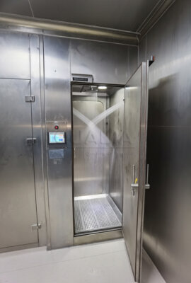
La secuencia de apertura de las puertas y el tiempo de permanencia en la esclusa son los puntos en los que se concentra esa vulnerabilidad. Cuando un operador atraviesa una esclusa, tanto el límite de presión interior como el exterior quedan expuestos brevemente a un estado común. La esclusa recupera su diferencial de presión solo después de que se cierre la primera puerta, la zona se repressurice con respecto al pasillo y la segunda puerta quede entonces lista para abrirse. Si el tiempo de permanencia —el periodo comprendido entre la entrada en la esclusa y el momento en que la primera puerta completa su ciclo de cierre automático— es demasiado corto para que la zona se estabilice, la segunda puerta se abre a una condición de presión que aún no es representativa del diferencial en estado estacionario para el que se diseñó el sistema.
La implicación práctica para la planificación en cascada es que el tiempo de permanencia debe determinarse en función de la velocidad de respuesta de la compuerta, y no solo en función de la comodidad del operador. Una esclusa que tenga capacidad física para una persona y su EPI, pero cuyo enclavamiento libere la segunda puerta antes de que se haya restablecido el diferencial de presión entre zonas, proporciona una transición de contención incompleta. Se trata de una decisión de especificación que requiere la participación tanto del equipo de puesta en servicio del sistema de climatización como del diseñador de los controles de enclavamiento —dos grupos que, en muchos proyectos, no comparten un hito de revisión común hasta que la puesta en servicio ya está programada—.
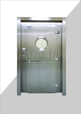
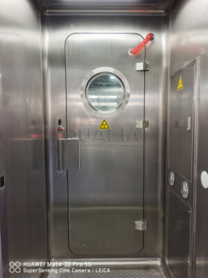
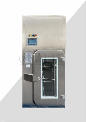
Para aplicaciones de nivel BSL-3, junta neumática puertas APR garantizan la integridad del sellado que permite verificar el funcionamiento del cierre automático en condiciones de presión, pero la especificación de los herrajes de la puerta por sí sola no resuelve la cuestión del tiempo de permanencia. Para determinarlo es necesario saber con qué rapidez se estabiliza la zona de la esclusa de aire tras el cierre de la puerta exterior, lo cual es una característica de la respuesta del sistema de climatización, no de la puerta. Los equipos que especifican las puertas y el sistema de climatización de forma independiente, sin un modelo de rendimiento común para el periodo de recuperación de la esclusa de aire, suelen descubrir esta falta de sincronización durante la puesta en marcha, en lugar de durante la fase de diseño.
Respuesta de las compuertas y movimientos del operador en condiciones de ocupación
El funcionamiento en estado de ocupación introduce una variabilidad en la presión que no aparece en ningún modelo de estado estacionario. El diferencial de la cascada, que se lee correctamente un lunes por la mañana sin ocupantes ni campanas extractoras activas, puede fluctuar de forma significativa durante un turno de trabajo, cuando cambian las posiciones de las ventanas, el personal se desplaza entre zonas y el sistema VAV del edificio responde a las cargas térmicas en otras partes de las instalaciones.
Si no se tiene en cuenta esta dinámica de los estados ocupados en el diseño, se está aceptando que la cascada funcionará periódicamente fuera de su banda diferencial prevista sin que se active ninguna medida correctiva, lo que supone un riesgo de contención que no se refleja en los datos estáticos de puesta en servicio.
| Factor de los Estados ocupados | Cómo altera la cascada | Respuesta de diseño |
|---|---|---|
| Ventanillas ajustables para campanas extractoras | Los ajustes rápidos de las hojas provocan cambios bruscos de presión que pueden desestabilizar los diferenciales. | Utiliza válvulas de aire tipo Venturi para reaccionar rápidamente y estabilizar la presión |
| Fluctuaciones de presión en los edificios (VAV/economizadores) | Las variaciones en los sistemas de climatización externos alteran la presión en los pasillos, lo que conlleva el riesgo de un fallo en cadena | Diseñar la respuesta de las compuertas para mantener una presión constante en el conducto en condiciones variables de suministro y extracción. |
La consecuencia de pasar por alto cualquiera de estas fuentes de perturbación en la fase de diseño no es simplemente que las alarmas se activen con mayor frecuencia. Es que la cascada puede fallar de forma transitoria —la presión se invierte brevemente o cae por debajo del diferencial mínimo— en condiciones que se dan habitualmente durante el funcionamiento normal con ocupantes. Ese fallo transitorio es precisamente lo que la cascada pretende evitar, y no quedará detectado por un protocolo de validación que solo realice pruebas en una única condición de estado estacionario, con las puertas cerradas y sin ocupantes presentes.
Comparación entre los cálculos de presión estática y el comportamiento real de los ciclos de apertura y cierre de las puertas
Los planos de presión estática representan un modelo de la instalación en condiciones ideales: todas las penetraciones selladas, todas las puertas cerradas, todos los flujos de aire en sus valores de consigna de diseño y sin perturbaciones transitorias derivadas de la ocupación del edificio o del funcionamiento de los equipos. Ese modelo resulta útil para el dimensionamiento del sistema y para establecer la jerarquía de presión prevista, pero no puede sustituir a la validación en condiciones reales de apertura y cierre de las puertas.
La diferencia entre lo que se supone en los planos estáticos y lo que ocurre realmente durante el ciclo de apertura y cierre de las puertas sigue un patrón reconocible en todas las instalaciones de nivel BSL-3.
| Lo que se da por supuesto en los planos estáticos | ¿Qué ocurre durante el ciclo de apertura y cierre de puertas? | Por qué es importante |
|---|---|---|
| Las puertas se cierran automáticamente y mantienen el sellado | Las puertas que no se cierran automáticamente o que carecen de burletes adecuados interrumpen la cascada | Se produce un fallo en la cascada, lo que requiere volver a realizar las pruebas o modificar los enclavamientos |
| La estructura es lo suficientemente resistente como para soportar las presiones previstas en el diseño | Las fugas a través de las penetraciones, los techos con juntas y los suelos provocan dificultades para equilibrar el sistema. | Inestabilidad en cascada e incapacidad para mantener los diferenciales de diseño |
| La ubicación del sensor de presión del pasillo refleja el diferencial de presión de la esclusa de aire | La dinámica de los ciclos de apertura y cierre de las puertas provoca lecturas diferenciales incorrectas durante el funcionamiento | Riesgo de una falsa sensación de seguridad respecto a la contención o de activaciones innecesarias de las alarmas |
Cada fila de esa comparación representa una situación en la que una instalación puede parecer que cumple con la intención de diseño sobre el papel, pero que, en la práctica, no logra mantener la contención. Lo que hace que este patrón sea relevante es que los fallos no son independientes: una instalación con fugas moderadas en la construcción, una puerta que tarda en cerrarse automáticamente y un sensor de presión colocado para garantizar la precisión en estado estacionario acumulará errores simultáneamente, y ninguno de esos errores será visible hasta que se realicen pruebas de ciclos de la puerta en condiciones que se aproximen a la ocupación real.
La implicación práctica es que la verificación de la presión durante la puesta en marcha debe incluir pruebas dinámicas: puertas sometidas a ciclos activos, observación de las zonas para detectar diferencias en el tiempo de recuperación y comprobación cruzada de las lecturas de los sensores con el comportamiento real de la presión durante el ciclo. La verificación diferencial estática confirma que el sistema de climatización puede alcanzar el valor objetivo; no confirma que la cascada mantenga dicho valor durante las transiciones que se producen docenas de veces por turno de ocupación. Para los equipos que diseñan el protocolo de validación, ISO 14644-3:2019 ofrece un marco reconocido para los métodos de ensayo en salas blancas y entornos controlados, incluyendo enfoques que pueden adaptarse para confirmar la dirección del flujo de aire y la integridad de la presión en condiciones dinámicas. La visualización del humo, en particular, es un método de bajo coste y de interpretación inmediata que permite confirmar que la dirección del flujo de aire a través del límite de una puerta se comporta según lo previsto durante el ciclo de apertura y cierre, y no solo antes y después del mismo.
Una observación sobre la estanqueidad de la construcción que a menudo se subestima en la fase de especificación: las fugas de laboratorio a través de las penetraciones, los dispositivos de techo con juntas y las uniones entre suelo y pared son ampliamente reconocidas por los equipos de puesta en servicio como la razón principal por la que el equilibrado de presión lleva más tiempo del previsto. Sellar estos elementos según un estándar que admita el diferencial de la cascada no es un detalle de acabado, sino una condición previa para que la cascada sea factible en absoluto. Tratarlo como tal durante la revisión del diseño, en lugar de como un punto más de la lista de tareas pendientes, reduce significativamente la probabilidad de tener que realizar un costoso reequilibrio tras la entrega de la obra.
Más barreras de aislamiento frente a la facilidad de uso diario
La incorporación de barreras de aire refuerza cada transición de contención de forma individual. Cada nivel de presión adicional entre el núcleo BSL-3 y el pasillo crea un diferencial menor que gestionar en cada puerta, reduce las consecuencias de cualquier incidente que se produzca en una sola puerta y proporciona una zona adicional de presión intermedia que limita la vía de exposición durante las entradas y salidas normales. Desde el punto de vista de la ingeniería de contención, un mayor número de barreras supone, sin lugar a dudas, una mayor protección.
La disyuntiva es de carácter operativo y se acumula a lo largo de la vida útil de la instalación, en lugar de ser una decisión de aceptación puntual. Cada límite adicional de la esclusa introduce al menos una relación de enclavamiento adicional que debe mantenerse, someterse a pruebas a intervalos regulares y mantenerse coordinada con la lógica de los controles del sistema de climatización. También introduce una restricción de comportamiento adicional para cada persona que entra o sale de la instalación cada día: un periodo de permanencia, una secuencia de puertas, una confirmación de que la zona anterior se ha reestabilizado.
En entornos de investigación de alto rendimiento, esa limitación se traduce en un obstáculo operativo significativo. Los equipos que trabajan con equipos de gran tamaño, que realizan traslados frecuentes de material o en los que varios ocupantes se desplazan en flujos de trabajo coordinados se enfrentan a la secuencia de esclusas como un factor limitante que afecta a la programación, y no solo a la comodidad. Esto no significa que un menor número de barreras sea la opción adecuada para aplicaciones en las que la contención es fundamental, sino que la decisión sobre cuántas barreras incluir debe tomarse teniendo en cuenta de forma realista la carga que supone el mantenimiento de los sistemas de enclavamiento y la carga operativa diaria, y no solo en función de la máxima protección alcanzable.
La consecuencia de no lograr este equilibrio, al establecer un número insuficiente de barreras, es que la instalación depende en mayor medida del cumplimiento de los procedimientos para gestionar las transiciones de contención que una esclusa adicional habría gestionado de forma mecánica. El cumplimiento de los procedimientos es más difícil de auditar, más difícil de garantizar de forma coherente a lo largo de los cambios de turno y la rotación de personal, y más difícil de defender en una inspección reglamentaria que una secuencia controlada por un sistema de enclavamiento. Para las instalaciones de nivel de seguridad biológica 3 (BSL-3) que operan bajo la supervisión de las autoridades de salud laboral, esa distinción es importante cuando se solicita la documentación sobre la fiabilidad de la contención.
Cometer un error al establecer demasiadas barreras conlleva un riesgo diferente: los operarios que consideren que el procedimiento es engorroso pueden desarrollar soluciones alternativas informales —como mantener las puertas abiertas, sincronizar las entradas para compartir un ciclo de la esclusa o eludir los enclavamientos durante los traslados de material— que anulen la protección que se pretendía ofrecer con esas barreras adicionales. Merece la pena analizar ambos modos de fallo en relación con los flujos de trabajo reales que se llevarán a cabo en la instalación antes de fijar el número de barreras de esclusa en el diseño esquemático.
Riesgos relacionados con el hardware, los sistemas de control y la coordinación de los sistemas de climatización
El problema estructural en la especificación de la cascada de BSL-3 radica en que los tres sistemas que deben funcionar conjuntamente —los herrajes de las puertas, las secuencias de control y los reguladores de climatización— suelen estar a cargo de diferentes equipos de especificación, se revisan en plazos distintos y se presentan en lotes de licitación diferentes. Cuando una instalación funciona correctamente, la coordinación ha funcionado. Cuando falla, a menudo resulta imposible atribuir el fallo a un único equipo, ya que el modo de fallo requiere una combinación específica de condiciones en los tres sistemas simultáneamente.
La tabla que figura a continuación recoge tres deficiencias de coordinación que, consideradas individualmente, parecen manejables, pero que, en conjunto, representan el patrón más habitual de problemas en cadena tras la finalización de la obra.
| Falta de coordinación | Por qué es importante | Qué aclarar |
|---|---|---|
| El aire se cuela por los orificios de la cerradura de la puerta | Las fugas a través de las aberturas de las válvulas provocan una pérdida de presión en cascada | Los marcos de las puertas deben ser herméticos por dentro para eliminar las vías de fuga. |
| No hay supervisión continua ni suministro eléctrico de emergencia | Un fallo en el suministro eléctrico o en los equipos puede provocar una pérdida de contención que pase desapercibida. | Requiere una supervisión continua de la presión, alarmas y un suministro eléctrico de emergencia |
| Saturación del filtro HEPA y compatibilidad del equipo | La acumulación de suciedad en el filtro aumenta la resistencia al flujo de aire; la incompatibilidad con las cabinas de bioseguridad o los equipos de descontaminación puede interrumpir la cascada | Comprobar el rendimiento del sistema en cascada en condiciones de filtro cargado y garantizar la compatibilidad con todos los equipos instalados |
La vía de fuga de aire a través de los orificios del cilindro de la cerradura de la puerta es un ejemplo concreto que merece la pena mencionar precisamente porque suele pasar desapercibido durante la revisión del diseño. Una especificación del marco de la puerta que cumpla los requisitos estructurales y de estanqueidad en la superficie frontal puede seguir presentando vías de fuga a través de la carcasa del mecanismo de la cerradura si el marco no está sellado internamente en el punto donde el cilindro de la cerradura atraviesa el cuerpo del marco. Se trata de un detalle de fabricación, no de un error de diseño, y es precisamente el tipo de hueco que queda entre la especificación de los herrajes de la puerta y la especificación de rendimiento del sistema de climatización, sin que sea responsabilidad de ninguno de los dos equipos. En el caso de las instalaciones que utilizan sistemas de puertas con sellado mecánico, cierre mecánico puertas APR Aunque la construcción hermética del marco soluciona esta vulnerabilidad por diseño, el requisito de estanqueidad interna debe confirmarse como un elemento de la especificación, y no darse por sentado.
La consecuencia más amplia de que estas deficiencias se den de forma conjunta —una vía de fuga no detectada, la ausencia de un protocolo de alimentación de emergencia para la monitorización de la presión y un modelo de rendimiento en cascada que se validó antes de que los filtros HEPA comenzaran a saturarse— es que la instalación pueda funcionar dentro de los valores aceptables durante la puesta en marcha inicial y desviarse de ellos en los meses siguientes sin que se active la auditoría o la investigación que revelaría la causa. La monitorización continua de la presión con alarmas calibradas, probadas en situaciones de alimentación de emergencia, es el control que permite detectar esa desviación antes de que se convierta en un incidente de contención.
La acumulación de partículas en los filtros HEPA merece una atención especial en el debate sobre la coordinación de los controles. A medida que los filtros se van saturando a lo largo de su vida útil, aumenta la resistencia al flujo de aire a lo largo del recorrido de extracción, y el sistema de climatización debe compensar esta resistencia para mantener el mismo volumen de extracción. Si el modelo de rendimiento en cascada se validó en condiciones de filtros limpios y los controles no están configurados para adaptarse al aumento de la resistencia, el diferencial en cascada se reducirá a medida que los filtros se acerquen a su punto de sustitución —un periodo que puede prolongarse durante meses, durante el cual la jerarquía de contención funciona por debajo de su margen de diseño previsto—. La validación del rendimiento de la cascada en condiciones de filtros cargados, o al menos la especificación de una lógica de control que mantenga los puntos de consigna del diferencial a medida que aumenta la resistencia de los filtros, debería formar parte del alcance de la puesta en servicio, y no ser una preocupación de mantenimiento futura.
Disparador de validación en cascada para los límites de contención de nivel BSL-3
La validación de la contención de una cascada de presión de nivel BSL-3 debe centrarse en las condiciones en las que es más probable que la cascada falle, y no en aquellas en las que resulte más fácil realizar las mediciones. Esa distinción determina qué se somete a ensayo, cuándo se programan los ensayos y cómo se interpretan los resultados.
Las cifras de diferencia de presión a las que se hace amplia referencia en las directrices para profesionales ofrecen un marco inicial útil: el diseño debe fijarse en un objetivo de aproximadamente 0,1 pulgadas de columna de agua (in wg) en cada etapa de la cascada, considerando 0,05 in wg como la diferencia mínima aceptable y 0,2 in wg como el límite superior que permite una variación operativa normal sin activar alarmas innecesarias. No se trata de umbrales reglamentarios de obligado cumplimiento universal, sino que representan un punto de equilibrio que, según han constatado los profesionales con experiencia, ofrece un margen suficiente para las fluctuaciones del mundo real sin que la cascada resulte tan sensible que active alarmas ante transitorios de presión rutinarios. Las instalaciones deben considerarlos como objetivos de diseño que deben confirmarse en función del comportamiento específico de su sistema de climatización y de los patrones de ocupación, y no como requisitos de cumplimiento fijos.
| Elemento de validación | Umbral o método | Propósito |
|---|---|---|
| Objetivos de diferencia de presión | Diseñar para 0,1 pulgadas de columna de agua (mínimo 0,05 pulgadas de columna de agua), sin superar las 0,2 pulgadas de columna de agua. | Proporciona una cascada estable que permite una variación normal sin que se activen las alarmas |
| Enfoque de equilibrado del flujo de aire | El caudal de aire de salida es aproximadamente 15% mayor que el de entrada; equilibra primero el aire de salida y, a continuación, el de entrada. | Establece una jerarquía de presión negativa y simplifica la configuración |
| Pruebas de puesta en servicio | Visualización de humo, verificación de la presión diferencial, integridad de los filtros HEPA, comprobaciones del funcionamiento de las alarmas | Valida la cascada en condiciones reales de ocupación, no solo con lecturas estáticas |
El enfoque de equilibrado que se muestra en la tabla —fijar el volumen de extracción en aproximadamente 15% por encima del volumen de impulsión antes de ajustar este último— refleja una secuencia práctica de puesta en servicio que establece la referencia de presión negativa antes de introducir la variable del lado de impulsión. Empezar por el aire de extracción garantiza que la dirección del flujo de aire sea la correcta antes de ajustar con precisión la magnitud del diferencial. Se trata de un detalle del proceso derivado de la experiencia de los profesionales, no de un método universalmente prescrito, pero evita una ineficiencia habitual en la puesta en marcha, en la que el aire de impulsión y el de extracción se ajustan de forma iterativa sin un punto de referencia estable.
Las pruebas de puesta en servicio más importantes para la validación en cascada son aquellas que revelan lo que las lecturas estáticas no pueden mostrar: la visualización del humo durante el ciclo activo de las puertas para confirmar que el flujo de aire direccional se mantiene durante el evento de transición; la verificación de la presión diferencial con ocupantes presentes y las ventanas de las campanas extractoras en posiciones variables; las pruebas de integridad de los filtros HEPA que tienen en cuenta las condiciones de resistencia a las que se verá sometido el sistema durante su funcionamiento; y las comprobaciones funcionales de las alarmas que confirman que el sistema de monitorización responde correctamente a los umbrales diferenciales específicos que ha establecido la instalación. Las directrices del Manual de Bioseguridad en Laboratorios de la OMS sobre el diseño de laboratorios de contención refuerzan el principio de que la puesta en servicio debe confirmar el rendimiento en las condiciones en las que la instalación funcionará realmente, y no solo en condiciones de referencia idealizadas.
El criterio de validación de la cascada debe ser el escenario de estado ocupado, no la lectura de sala vacía. Una cascada que mantenga 0,1 en wg con las puertas cerradas y sin ocupantes es una condición necesaria para el cumplimiento normativo, pero no es una condición suficiente para garantizar la contención. La condición suficiente es una cascada que mantenga su diferencial a lo largo de los ciclos de apertura y cierre de puertas, los ajustes de las hojas y las fluctuaciones del VAV que se producen durante un turno normal con ocupantes, y que recupere su punto de consigna en un intervalo de tiempo para el que los controles y la lógica de enclavamiento hayan sido configurados específicamente.
La decisión más trascendental en la planificación de la cascada de un laboratorio de nivel de seguridad biológica 3 (BSL-3) es determinar en qué momento del calendario del proyecto se deben probar las condiciones que realmente someten al sistema a estrés. Los equipos que limitan la validación a lecturas estáticas en salas vacías pondrán en servicio una instalación que cumpla con sus objetivos de diseño sobre el papel, pero que aún así podría sufrir fallos en la cascada durante su uso operativo —fallos que requieren cambios en los enclavamientos, trabajos de reequilibrio y, en algunos casos, modificaciones estructurales una vez que la instalación ya está terminada—. El rango de diferencial de 0,05 a 0,1 pulgadas de columna de agua (wg) que la cascada está diseñada para mantener no deja prácticamente ningún margen para la acumulación de fugas, la deriva en la carga de los filtros y las fluctuaciones del sistema de climatización, que se agravan una vez que la instalación entra en funcionamiento.
Antes de ultimar el protocolo de validación, conviene confirmar tres aspectos: que el alcance de la puesta en servicio incluya pruebas dinámicas de ciclos de las puertas con ocupantes presentes, y no solo lecturas diferenciales en estado estacionario; que los equipos de herrajes de puertas, climatización y automatización de edificios hayan revisado conjuntamente las especificaciones de los controles, comparándolas con la secuencia de enclavamiento real tal y como se ha instalado; y que el modelo de rendimiento en cascada tenga en cuenta la resistencia al final de la vida útil del filtro, y no solo las condiciones con el filtro limpio. Esas tres confirmaciones, realizadas antes de programar la puesta en servicio y no durante la misma, son las que suelen marcar la diferencia entre una cascada que funciona correctamente y otra que requiere costosas correcciones tras la entrega.
Preguntas frecuentes
P: Nuestras instalaciones cuentan con una única puerta de entrada sin cámara de compensación específica; ¿se siguen aplicando en este caso las directrices sobre la cascada de presión?
R: Se aplican los principios básicos, pero el margen de contención se reduce significativamente y la carga procedimental aumenta de forma sustancial. Una entrada de una sola puerta implica que el pasillo y el núcleo BSL-3 comparten una barrera de presión directa cada vez que se abre la puerta, sin zona de recuperación intermedia. El tiempo de permanencia y la lógica de recuperación diferencial descritos para las esclusas de aire no tienen equivalente mecánico en una configuración de una sola puerta, por lo que toda la transición depende de la velocidad de cierre automático de la puerta, la estanqueidad de la construcción y la disciplina del operador. En esta configuración, los modos de fallo relacionados con el ciclo de la puerta y las fluctuaciones del VAV que el artículo identifica para las esclusas de aire cobran mayor importancia, no menor, y resulta más difícil demostrar la justificación normativa ante incidentes de contención sin una secuencia controlada por enclavamientos.
P: Una vez que las pruebas de puesta en servicio hayan dado lecturas estáticas aceptables, ¿cuál debería ser el siguiente paso operativo inmediato antes de que el personal comience con el trabajo habitual?
R: El siguiente paso inmediato es llevar a cabo una verificación en estado de ocupación con flujos de trabajo activos antes de que comience el uso rutinario; no se debe considerar que haber superado la puesta en marcha estática supone la autorización para iniciar las operaciones normales. Esto implica realizar pruebas de ciclos de las puertas con personal presente, confirmar los tiempos de recuperación diferenciales según los patrones de movimiento reales y verificar que los umbrales de alarma se comportan correctamente cuando se ajustan las ventanas de las campanas extractoras durante la ocupación. La puesta en marcha estática confirma que el sistema de climatización puede alcanzar los objetivos de diseño en condiciones ideales; no confirma que la cascada se mantenga durante las transiciones que se producirán docenas de veces por turno. Considerar las pruebas dinámicas en estado de ocupación como un hito posterior a la puesta en marcha, en lugar de como una condición para la autorización, es el paso que cierra la brecha entre el cumplimiento sobre el papel y la garantía de contención operativa.
P: ¿En qué momento el diseño para un diferencial de presión más ajustado deja de mejorar la contención y empieza a generar problemas operativos?
R: El límite superior del beneficio práctico se sitúa en torno a 0,2 pulgadas de columna de agua por etapa de la cascada, y superarlo suele generar más problemas de los que resuelve. Por encima de ese umbral, los transitorios de presión habituales provocados por el ciclo de apertura y cierre de puertas, las fluctuaciones del VAV y los ajustes de las hojas de las ventanas activarán alarmas con tanta frecuencia que los operadores empezarán a considerar los eventos de alarma como ruido de fondo en lugar de señales significativas, lo que anula por completo la función de monitorización. Un diferencial más estrecho también hace que la cascada sea más sensible a la acumulación de fugas y a la deriva en la carga de los filtros que se producen durante la vida útil normal de la instalación, lo que reduce el margen operativo hasta el punto de que el sistema requiere un reequilibrio antes de lo previsto. El mínimo de 0,05 pulgadas de columna de agua y el objetivo de diseño de 0,1 pulgadas de columna de agua representan un rango que, según han comprobado los profesionales con experiencia, proporciona un margen de contención real al tiempo que tolera la variabilidad que introduce el funcionamiento en condiciones reales.
P: ¿Cómo influye la elección entre puertas APR con sellado neumático y sellado mecánico en los riesgos de coordinación entre los equipos de hardware, controles y climatización?
R: La elección determina qué deficiencias de coordinación requieren mayor atención, más que eliminarlas. Las puertas con sellado neumático introducen una dependencia del suministro de aire comprimido que debe coordinarse con la planificación de la alimentación eléctrica de emergencia y la lógica de los controles; un fallo en el sistema neumático durante un turno en el que hay personal presente supone una vulnerabilidad en cadena, a menos que la secuencia de controles lo tenga en cuenta. Las puertas con sellado mecánico eliminan esa dependencia, pero requieren un sellado interno confirmado del marco en el punto de penetración del cilindro de la cerradura, lo cual es un detalle de fabricación que se sitúa entre la especificación de los herrajes de la puerta y la especificación de rendimiento del sistema de climatización si no es competencia explícita de un equipo concreto. Ambos tipos de puertas requieren la misma revisión interdepartamental de la secuencia de enclavamientos, el tiempo de permanencia y la recuperación diferencial: el mecanismo de sellado cambia los modos de fallo específicos a los que hay que prestar atención, pero no la necesidad de una revisión conjunta de las especificaciones.
P: ¿Es suficiente la norma de equilibrio entre extracción y suministro 15% para instalaciones con elevadas cargas térmicas internas o con varias cabinas de bioseguridad que se alimentan de la misma cámara de extracción?
R: No; la cifra 15% es una referencia práctica inicial para establecer la tendencia direccional del flujo de aire durante la puesta en marcha, no una regla de dimensionamiento para configuraciones complejas de extracción. Las instalaciones con cargas térmicas internas significativas, múltiples cabinas de bioseguridad de Clase II o campanas de extracción de flujo variable presentan demandas de extracción contrapuestas que pueden alterar el diferencial efectivo en los límites de la cascada de formas que un desplazamiento fijo de 15% no prevé. En estas configuraciones, las válvulas de aire tipo Venturi, que responden rápidamente a condiciones de caudal variable, cobran mayor importancia, y la secuencia de equilibrado debe tener en cuenta la demanda de extracción simultánea en el peor de los casos, y no solo el consumo medio o el de cada equipo individual. La regla 15% ayuda a establecer un punto de referencia estable antes de comenzar los ajustes de suministro; debe complementarse con un modelo de carga específico del sistema que tenga en cuenta la configuración real de los equipos de extracción y su variabilidad durante el uso con ocupación.